
Contactor failure detection method and contactor failure detection system

A detection system and detection method technology, applied in circuit breaker testing, instruments, measuring electricity and other directions, can solve problems such as difficulty in accurately judging whether the contactor needs to be replaced, user safety hazards, contactor failure, etc., to achieve effective detection , the effect of improving safety performance and improving applicability

Pending Publication Date: 2021-06-04
WUHAN TROOWIN POWER SYST TECH
View PDF8 Cites 0 Cited by
  • Summary
  • Abstract
  • Description
  • Claims
  • Application Information

AI Technical Summary

Problems solved by technology

[0003] The traditional contactor protection strategy is estimated based on the electrical life curve provided by the manufacturer. In fact, it is difficult to accurately judge the current state of the contactor, or wait for the contactor to fail before performing relevant protection on the system.
That is to say, once the contactor after leaving the factory is installed and used, it is usually replaced by a professional after a failure occurs, and it is difficult to detect whether the contactor is in normal working condition with the detection method of the prior art, which easily leads to The effectiveness of the contactor during use affects the normal operation of electrical equipment
On the other hand, based on the electrical service life curve provided by the contactor manufacturer, it is difficult to accurately judge whether the contactor needs to be replaced, and if the contactor is used beyond its service life, it is easy to cause safety hazards to users
[0004] In addition, the ambient temperature is also a major factor affecting whether the contactor can work normally. During the working process of the contactor, the resistance value of its own resistance will change with the change of the ambient temperature, and other factors in the environment will also cause the contactor to The resistance value of the resistor changes, which in turn affects the normal operation of the contactor, resulting in failure of the contactor

Method used


Image

  • Contactor failure detection method and contactor failure detection system
  • Contactor failure detection method and contactor failure detection system
  • Contactor failure detection method and contactor failure detection system

Examples


Embodiment Construction

[0037] The following description serves to disclose the present invention to enable those skilled in the art to carry out the present invention. The preferred embodiments described below are only examples, and those skilled in the art can devise other obvious variations. The basic principles of the present invention defined in the following description can be applied to other embodiments, variations, improvements, equivalents and other technical solutions without departing from the spirit and scope of the present invention.

[0038] Those skilled in the art should understand that in the disclosure of the present invention, the terms "vertical", "transverse", "upper", "lower", "front", "rear", "left", "right", " The orientation or positional relationship indicated by "vertical", "horizontal", "top", "bottom", "inner", "outer", etc. is based on the orientation or positional relationship shown in the drawings, which are only for the convenience of describing the present invention...


PUM


Abstract

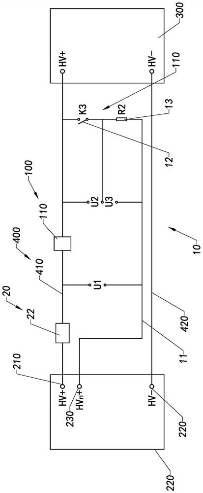
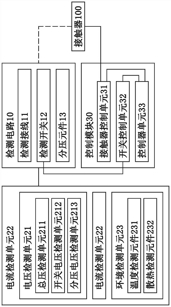
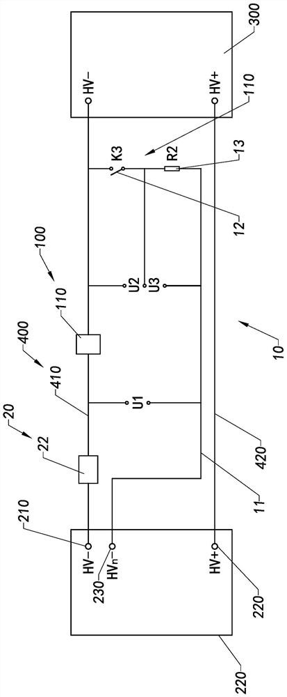
The invention provides a contactor failure detection method and a contactor failure detection system, the contactor failure detection system comprises a detection circuit, a detection module and a control module, the detection circuit is electrically connected with a battery module and a contactor to form a detection loop, the detection module is electrically connected to the detection circuit, the detection module detects current flowing through the contactor and partial voltage corresponding to the contactor so as to obtain the resistance value of a contact resistor of the contactor, and the control module is electrically connected to the detection circuit and the detection module, the detection module calculates the temperature rise of the contactor according to the data information detected by the detection module, and judges the validity of the contactor according to the real-time temperature of the contactor.

Description

technical field [0001] The invention relates to the field of electrical detection, in particular to a contactor failure detection method and a contactor failure detection system. Background technique [0002] Contactors are used in electric power, power distribution and power consumption occasions, among which contactors are the most used safety protection devices in the modern electrical industry, and their own failure will lead to serious electrical accidents. The failure protection of the contactor can better protect the entire electrical system. [0003] The traditional contactor protection strategy is estimated based on the electrical life curve provided by the manufacturer. In fact, it is difficult to accurately judge the current state of the contactor, or wait for the contactor to fail before performing relevant protection on the system. That is to say, once the contactor after leaving the factory is installed and used, it is usually replaced by a professional after ...

Claims


Application Information

Patent Timeline
Patent Type & Authority Applications(China)
IPC IPC(8): G01R31/327G01R31/00
CPCG01R31/327G01R31/003
Inventor 王安单胜军李平
Owner WUHAN TROOWIN POWER SYST TECH
Learn More