Rain gauge

A technology of rain gauge and optical measurement, which is applied in the field of rain gauge, can solve the problems of small measurement interval, inaccurate measurement, and excessive measurement, and achieve the effects of avoiding missed detection, improving accuracy, and avoiding repeated measurement

Active Publication Date: 2021-06-04
SHANDONG MEASUREMENT SCI RES INST +1
View PDF18 Cites 2 Cited by
  • Summary
  • Abstract
  • Description
  • Claims
  • Application Information

AI Technical Summary

Problems solved by technology

[0003] The invention provides a rain gauge, which solves the problem of inaccurate measurement caused by too small or too large measurement intervals of optical rain gauges in the prior art

Method used


Image

  • Rain gauge
  • Rain gauge
  • Rain gauge

Examples


Embodiment 1

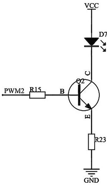
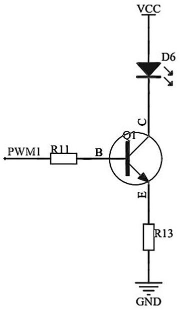
[0028] Such as figure 1 and Figure 4-9 As shown, a rain gauge includes an optical metering module, a piezoelectric counting module and a control circuit, the optical metering module is fixedly connected to the piezoelectric counting module, and the optical metering module and the piezoelectric counting module are respectively electrically connected to the control circuit; the optical metering module It includes a light guide cover 1, a light source 2 and a detection module 3 arranged opposite to the light source 2. When the present invention is used, when the piezoelectric counting module collects the signal, the relevant signal is transmitted to the control circuit, and the control circuit makes the light source 2 emit light. After the detection module 3 receives the light signal, it is converted into an electrical signal and transmitted to the control circuit. If there is attenuation, it proves that rainwater falls on the light guide cover 1, and the size of the raindrop i...

Embodiment 2

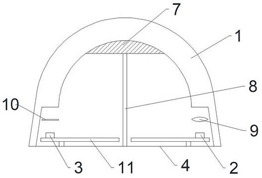
[0036] Such as figure 2As shown, the difference between this embodiment and Embodiment 1 is that the piezoelectric counting module also includes a second base 5, an arched thin steel plate (vibration plate 6) is provided at the opening at the upper end of the second base 5, and the light guide cover 1 is fixed On the arched thin steel plate, the control circuit is located in the second base 5, the light source 2 and the detection module 3 are located in the enclosed area surrounded by the light guide cover 1 and the arched thin steel plate, and the light source 2 and the detection module 3 pass through the arched thin steel plate respectively. The wire of the shaped thin steel plate is connected with the control circuit. The wires are supported by the support member 8 to avoid direct contact with the arched thin steel plate and hinder the vibration of the arched thin steel plate. The convex lens and the optical filter are also fixed on the second base 5 by the support member ...

Embodiment 3

[0039] Such as image 3 As shown, the difference between this embodiment and Embodiment 2 is that the light guide cover 1 is sealed and connected with the plastic sheet (vibration plate 6), and the piezoelectric pressure sensor is fixedly installed on the second base 5 through the support 8 passing through the plastic sheet. , the piezoelectric device 7 is attached to the inner surface of the light guide cover 1 . When raindrops or debris fall on the light guide cover 1, the plastic sheet will be deformed, and pressure will be applied to the piezoelectric device 7, and the piezoelectric device 7 will generate current and transmit it to the control circuit, which controls the optical detection Module 3 performs detection.


PUM


Abstract

The invention relates to the technical field of rainfall measurement, and solves the problem of inaccurate measurement caused by too small or too large measurement interval of an optical rain gauge in the prior art. A rain gauge comprises an optical metering module, a piezoelectric counting module and a control circuit, the optical metering module is fixedly connected with the piezoelectric counting module, and the optical metering module and the piezoelectric counting module are electrically connected with the control circuit. The optical metering module comprises a light guide cover, a light source and a detection module opposite to the light source. When the piezoelectric counting module is activated once, the optical metering module works once, and each drop of rainwater falling on the light guide cover is counted and metered, so that repeated measurement of the raindrops is avoided, missing detection is also avoided, and the measurement accuracy is improved.

Description

technical field [0001] The invention relates to the technical field of precipitation measurement, in particular to a rain gauge. Background technique [0002] The optical rain gauge has an infrared light source. The infrared light emitted by the infrared light source propagates in the transparent upper cover, and is totally reflected at the interface between the upper cover and the air, and finally reaches the photodiode. When there is rain on the surface of the upper cover, due to the refraction of the rainwater The refractive index of the infrared light is greater than the refractive index of the air, and the infrared light no longer undergoes total reflection at the interface between the upper cover and the rainwater, but reflection and refraction occur, which causes the intensity of the infrared light received by the photodiode to weaken, and the conditioning circuit receives the electrical signal of the photodiode and outputs rainfall information. The optical rain gaug...

Claims


Application Information

Patent Timeline
Patent Type & Authority Applications(China)
IPC IPC(8): G01W1/14
CPCG01W1/14Y02A90/10
Inventor 张朝周在伟杨垒
Owner SHANDONG MEASUREMENT SCI RES INST
Why Eureka
Try Eureka