Arc extinguishing device of non-polar high-voltage direct-current contactor

A high-voltage DC, arc extinguishing device technology, applied in relays, electromagnetic relays, electromagnetic relay details and other directions, can solve the problem of arcing space unable to increase power, avoid occupying arc extinguishing room space, improve magnetic force utilization, improve The effect of the arc extinguishing effect

Pending Publication Date: 2021-06-04
苏州安来强电子科技有限公司
View PDF0 Cites 0 Cited by
  • Summary
  • Abstract
  • Description
  • Claims
  • Application Information

AI Technical Summary

Problems solved by technology

[0004] The problem to be solved by the present invention is to provide a non-polar high-voltage DC contactor arc extinguishing device to overcome the defect that the existing non-polar contactor cannot increase the power due to the limited arcing space

Method used


Image

  • Arc extinguishing device of non-polar high-voltage direct-current contactor
  • Arc extinguishing device of non-polar high-voltage direct-current contactor
  • Arc extinguishing device of non-polar high-voltage direct-current contactor

Examples


Embodiment 1

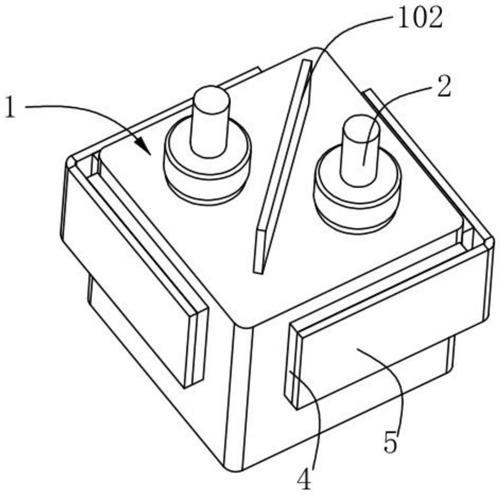
[0048] refer to Figure 3 to Figure 7 , the present invention provides a non-polar high-voltage DC contactor arc extinguishing device, comprising: an arc extinguishing cover 1, two static contacts 2 and a moving contact 3 installed on the arc extinguishing cover 1 at intervals, the extinguishing The arc extinguishing cover 1 is made of ceramic material, and the arc extinguishing cover 1 is sealed and fixedly connected with the magnetic guide plate of the contactor, and the inner cavity of the arc extinguishing cover 1 forms an arc extinguishing chamber 101 . The bottoms of the two static contacts 2 extend into the arc extinguishing chamber 101, the moving contact piece 3 is movably placed in the arc extinguishing chamber 101 and is facing the bottom of the two static contacts 2, the moving contact piece 3 can be opposite to the two static contacts 2 moves upwards to contact two static contacts 2, and then conducts the two static contacts 2.

[0049] refer to Figure 4 , the ...

Embodiment 2

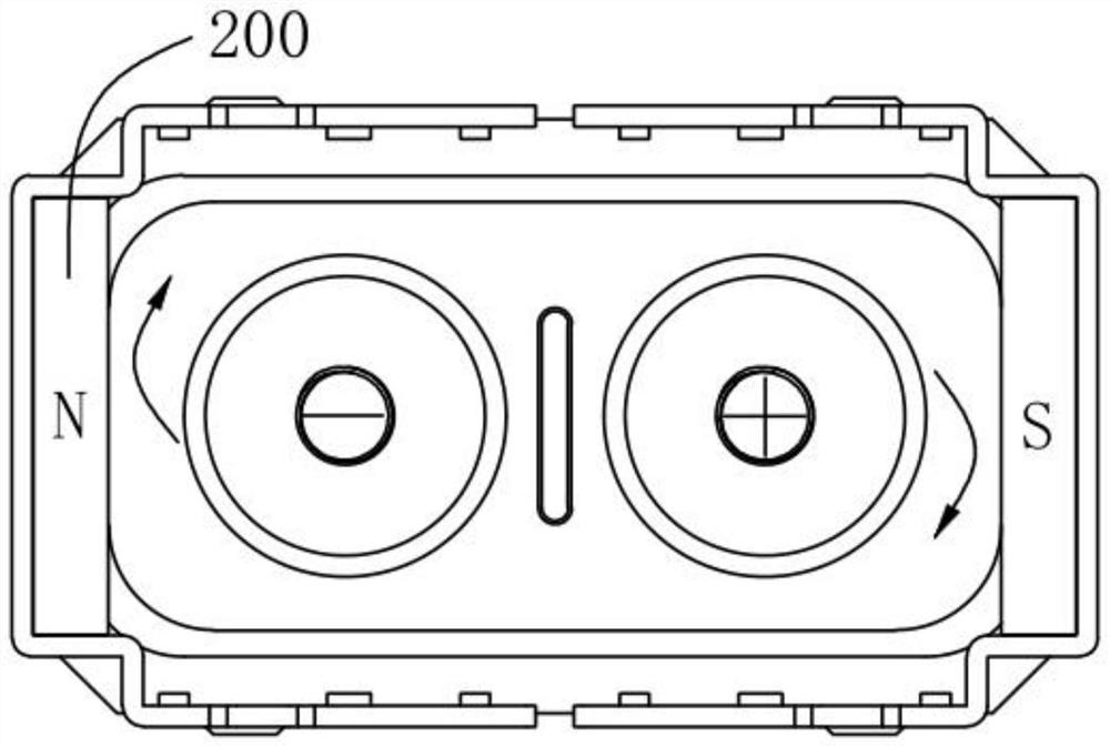
[0058] refer to Figure 8 The difference between this embodiment and Embodiment 1 is that the polarities of the two permanent magnets 4 corresponding to the arcing space 1011 on the same side are different, and the polarities of the two permanent magnets 4 located at the same angle are also different, that is, the four permanent magnets 4 , any two adjacent permanent magnets 4 have different polarities. Specifically: the four permanent magnet poles located at the upper left, lower left, upper right, and lower right are respectively N pole, S pole, S pole, and N pole. The permanent magnet 4 is placed in the same principle as above, regardless of the direction of the current, the arcs generated by the two static contacts 2 can be directed upward or downward into the arcing space 1011 without causing collision of the arcs, realizing No polarity required.

Embodiment 3 Embodiment 4

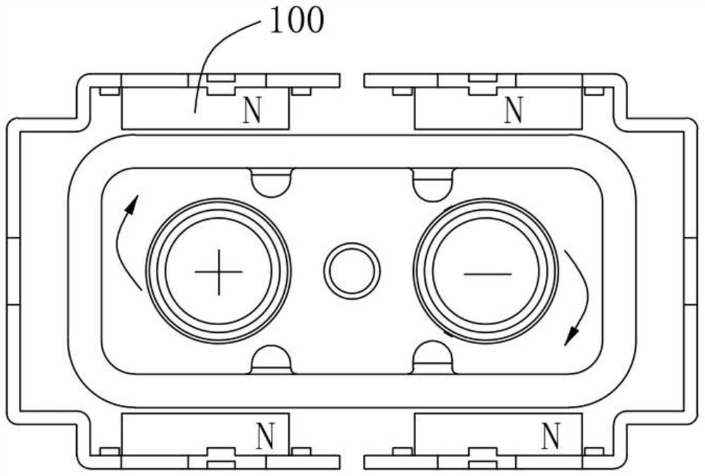
[0060] refer to Figure 9 and Figure 10 , are respectively the arrangement of the permanent magnets 4 of the third embodiment and the fourth embodiment, the difference from the first embodiment is that permanent magnets 4 with the same polarity are installed on the four side walls of the arc extinguishing cover 1 . Wherein, the polarities of the four permanent magnets 4 in the third embodiment are all N poles, and the polarities of the four permanent magnets 4 in the fourth embodiment are all S poles. Example 3 is used to illustrate: the static contact 2 located on the left is under the joint action of two permanent magnets 4 distributed close to the same angle, and the magnetic force vector it receives is directed to the left, and according to the left-hand rule, the arc will be directed upward Or in the lower arcing space 1011, the specific direction depends on the current flow direction. The arc generated by the static contact 2 on the right will also lead to the same arc...


PUM


Abstract

The invention discloses an arc extinguishing device of a non-polar high-voltage direct-current contactor. The device comprises an arc extinguishing cover body, two static contacts and a movable contact piece, the two static contacts and the movable contact piece are arranged on the arc extinguishing cover body in a spaced mode, and an inner cavity of the arc extinguishing cover body forms an arc extinguishing chamber; the movable contact piece is arranged in the arc extinguishing chamber and can move relative to the two static contacts to conduct the two static contacts, arc discharge spaces are formed in the arc extinguishing chamber and located on the two sides of a connecting line of the two static contacts, and at least one pair of permanent magnets is installed at the positions, corresponding to the arc discharge spaces, of the arc extinguishing cover body. And under the action of a magnetic field generated by a permanent magnet, electric arcs generated by the two static contacts move towards the arc discharge spaces. According to the arc extinguishing device of the non-polar high-voltage direct-current contactor, on the premise that the position of the static contacts is not changed, the maximum arc discharge spaces are guaranteed, the arc extinguishing effect is improved, and research and development of high-power non-polar products are completed in a limited space.

Description

technical field [0001] The invention relates to the field of contactors, in particular to an arc extinguishing device for a non-polar high-voltage DC contactor. Background technique [0002] The non-polar high-voltage DC contactor does not need to distinguish the forward and reverse of the current, and the two directions have the same electrical performance. It has great advantages in the use of non-polarity requirements such as car charging piles, photovoltaic industries, etc., and does not need to be distinguished during installation. The positive and negative poles of the contactor. However, the performance of the non-polar contactors currently on the market is greatly reduced, which cannot meet the needs of customers. [0003] The structure of the existing non-polar contactor is generally divided into two types: one is such as figure 1 As shown, the magnet A100 is installed on the front and rear sides facing the static contact, and the polarity of the magnet A100 is N ...

Claims


Application Information

Patent Timeline
Patent Type & Authority Applications(China)
IPC IPC(8): H01H9/44H01H50/38
CPCH01H9/443H01H50/38
Inventor 不公告发明人
Owner 苏州安来强电子科技有限公司
Why Eureka
Try Eureka