Photovoltaic module installation structure and photovoltaic system
An installation structure and photovoltaic module technology, applied in the support structure of photovoltaic modules, photovoltaic modules, photovoltaic power generation and other directions, can solve the problems of low photovoltaic module installation efficiency, frame fatigue failure, increased labor, etc., to improve the fixing effect and reduce stress. Concentration and strength-enhancing effects
- Summary
- Abstract
- Description
- Claims
- Application Information
AI Technical Summary
Problems solved by technology
Method used
Image


Examples
Embodiment 1
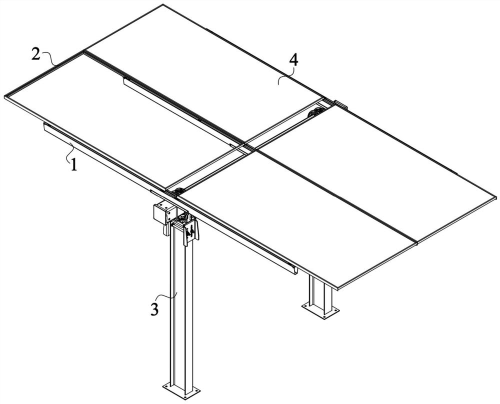
[0055] like figure 1 As shown, the present embodiment provides a photovoltaic system, including a laminate 4 and a photovoltaic component installation structure, and the photovoltaic component installation structure includes a frame 2, a guide rail 1 and a bracket 3. The laminate 4 is arranged on the frame 2, and the frame 2 is fixed on the guide rail 1. The photovoltaic module mounting structure can protect the laminate 4 and prevent the laminate 4 from being corroded or damaged by wind.
[0056] like figure 1 and figure 2 As shown, the laminate 4 has a rectangular structure, and the laminate 4 includes a front panel, a rear panel, and a string of battery cells disposed between the front panel and the rear panel. The cell string is composed of multiple cells. Multiple cells are connected in series to obtain high voltage first, and then connected in parallel to obtain high current. Then, a diode is used to prevent current from returning to output to achieve power output. B...
Embodiment 2
[0101] like Figure 9 As shown, the present embodiment provides a photovoltaic system, which is different from the first embodiment in that the guide rail 1 is also provided with a puncturing part 15, and the puncturing part 15 can puncture the protection during the installation process of the frame 2 layer and contact with the frame 2 so that the frame 2 can be reliably grounded.
[0102] like Figure 10 As shown, the piercing portion 15 includes an edge extending along the direction of the frame 2, and the edge can pierce the protective layer during the sliding process of the frame 2. Through the relative movement of the piercing portion 15 and the frame 2, the piercing effect is improved, So as to achieve a stable and continuous grounding effect.
[0103] In order to simplify the structure of the guide rail 1 and improve the piercing effect of the piercing part 15, the piercing part 15 can be formed by stamping the guide rail 1. Specifically, the guide rail 1 is provided...
PUM
 Abstract
Description
Claims
Application Information