Hotel management cleaning device

A cleaning device and hotel technology, applied in the field of hotel management, can solve the problems of time-consuming and labor-intensive, labor-intensive work, troublesome operation, etc.

Active Publication Date: 2021-06-08
CHONGQING VOCATIONAL INST OF ENG
View PDF7 Cites 0 Cited by
  • Summary
  • Abstract
  • Description
  • Claims
  • Application Information

AI Technical Summary

Problems solved by technology

[0004] Therefore, in the cleaning process of the corridor with a large width, since the cleaners need to constantly swing the suction head of the vacuum cleaner from side to side, the operation is troublesome, time-consuming and labor-intensive, and the work intensity is relatively high.

Method used


Image

  • Hotel management cleaning device
  • Hotel management cleaning device
  • Hotel management cleaning device

Examples


Embodiment 1

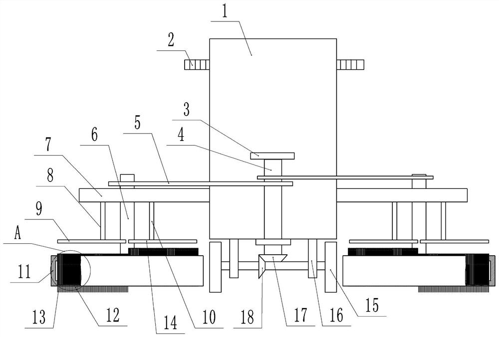
[0020] Basic as attached Figure 1-Figure 2 Shown: hotel management cleaning device, comprises car body 1, is welded with wheel frame 16 on the bottom of car body 1, and wheel frame 16 is connected with axle by bearing lateral rotation, and the two ends of wheel axle are fixedly connected with wheel 15 by flat key. The top of the car body 1 is welded with a handle 2 . The both sides of car body 1 are all provided with cleaning mechanism, and the cleaning mechanism structure of both sides is identical, and cleaning mechanism all comprises the fixed plate 7 that is fixedly connected on the side of car body 1 by screw, the vertical shaft 6 that is rotatably connected on the fixed plate 7 And the cleaning disc 11 fixedly connected to the bottom of the vertical shaft 6, the vertical shaft 6 in this embodiment is vertically arranged, the fixed plate 7 is placed horizontally, the vertical shaft 6 is connected to the fixed plate 7 through bearing rotation, and the cleaning disc 11 is ...

Embodiment 2

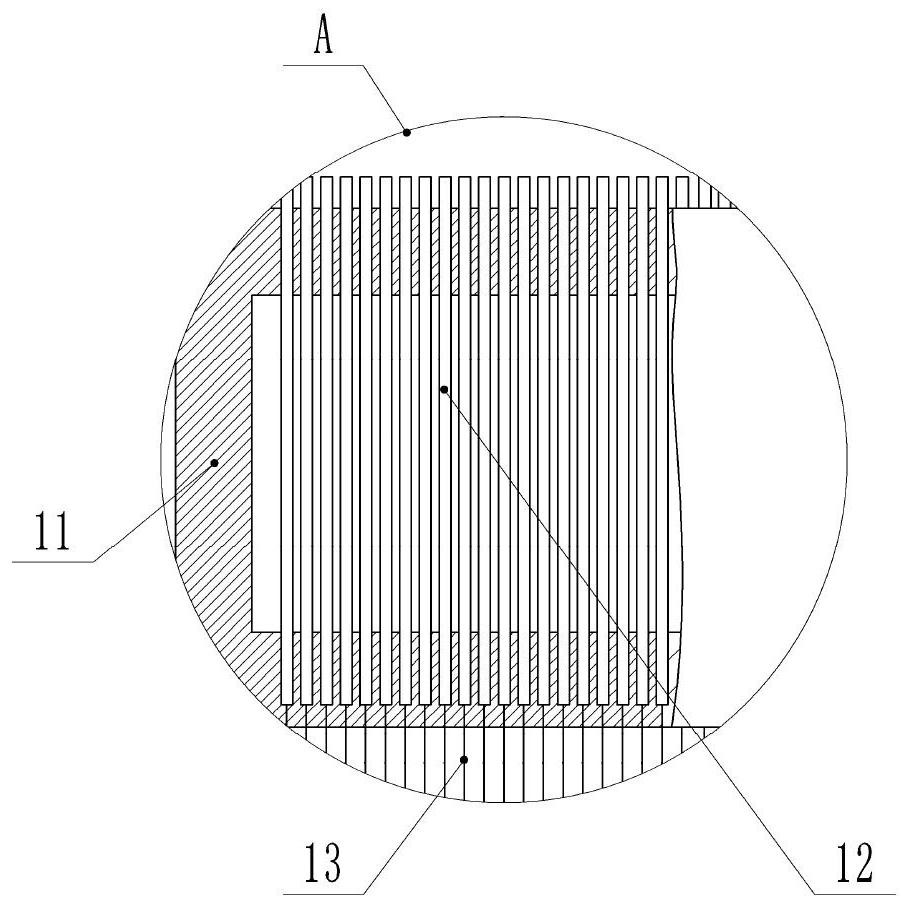
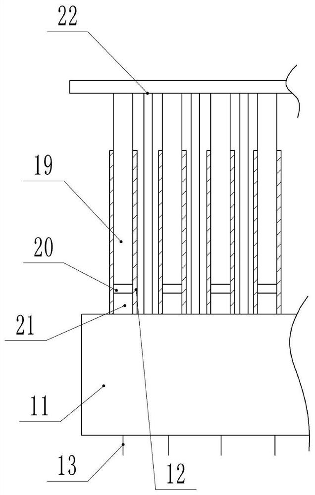
[0025] combine image 3 with Figure 4 As shown, in the present embodiment, the vertical rod 12 is provided with a vertical sliding cavity 21, the sliding cavity 21 is slidably connected with a piston 20, and the top of the piston 20 is bonded with a fixed rod 19 located above the cleaning disc 11. The fixed rod 19 The top of the top is positioned above the vertical rod 12, and the top of the cleaning disc 11 is provided with a rod frame 22. The rod frame 22 includes an integrally formed horizontal part and a vertical part, and the bottom end of the vertical part is bonded on the top of the cleaning disc 11. The vertical part is located in the gap between two adjacent vertical bars 12, and the top of the fixed bar 19 is bonded on the transverse part of the bar frame 22; the inside of the cleaning brush 13 is provided with a gas passage communicated with the sliding cavity 21 , The side wall of the cleaning brush 13 is provided with a plurality of capillary pores 23 communicat...


PUM


Abstract

The invention belongs to the field of hotel management and relates to a hotel management cleaning device. The hotel management cleaning device comprises a vehicle body; cleaning mechanisms are arranged on the two sides of the vehicle body; each cleaning mechanism comprises a fixing plate fixedly connected to the vehicle body, a vertical shaft rotationally connected to the fixing plate and a cleaning disc fixedly connected to the bottom of the vertical shaft, and a plurality of vertical holes are formed in the cleaning disc; vertical rods are vertically and slidably connected into the vertical holes; first magnets are fixedly connected to the tops of the vertical rods; cleaning brushes are fixedly connected to the bottoms of the vertical rods; brush holes are formed in the bottom of the cleaning disc; the cleaning brushes are vertically and slidably connected into the brush holes; second magnets and third magnets are fixedly connected to the fixing plate; the third magnets are located between the second magnets and the vehicle body; the opposite ends of the first magnets and the second magnets are identical in magnetism; the opposite ends of the first magnets and the third magnets are opposite in magnetism; and a driving mechanism for driving the vertical shaft to rotate is arranged on the vehicle body. According to the hotel management cleaning device provided by the technical schemes, the labor intensity for cleaning the ground with the large width is reduced.

Description

technical field [0001] The invention relates to the field of hotel management, in particular to a hotel management cleaning device. Background technique [0002] In hotel management, the ground needs to be cleaned regularly to ensure that the ground is clean and provide guests with a good living environment. [0003] When cleaning the ground, it is necessary to use tools such as a vacuum cleaner to clean the ground. For corridors with a large width, the dust and debris on the ground are relatively scattered, and the cleaners need to constantly swing the suction head of the vacuum cleaner from side to side to completely clean the left and right sides of the ground in the entire corridor without leaving any uncleaned to the place. [0004] Therefore, in the process of cleaning corridors with a larger width, since the cleaners need to constantly swing the suction head of the vacuum cleaner left and right, the operation is cumbersome, time-consuming and labor-intensive, and th...

Claims


Application Information

Patent Timeline
IPC IPC(8): A47L11/24A47L11/40
CPCA47L11/24A47L11/4038A47L11/4055A47L11/4069A47L11/40
Inventor 余海燕
Owner CHONGQING VOCATIONAL INST OF ENG
Why Eureka
Try Eureka