Water-bath quenching unit for steel wires

A water bath and steel wire technology, used in quenching devices, heat treatment equipment, manufacturing tools, etc., can solve the problems of no belt device, time, quenching length, the speed of cooling is difficult to control, and the quality of steel wires is not uniform, so as to ensure uniformity. , Improve the effect of water bath quenching effect

Active Publication Date: 2016-07-27
ZHANGJIAGANG DONGHANG MACHINERY
View PDF8 Cites 0 Cited by
  • Summary
  • Abstract
  • Description
  • Claims
  • Application Information

AI Technical Summary

Problems solved by technology

[0003] The isothermal water bath quenching unit for steel wire generally includes an upper quenching tank and a lower liquid storage tank. The quenching liquid is stored in the liquid storage tank and is circulated to the upper quenching tank. This isothermal water bath quenching unit has the following disadvantages: 1. The current upper Quenching tanks are only suitable for quenching steel wires with larger diameters, and steel wires with smaller diameters are more sensitive to temperature. The current upper quenching tanks are difficult to control the quenching time, quenching length, and cooling speed. When the quenching liquid flows in the upper quenching tank, the liquid level fluctuates relatively large, and the contact between the steel wire and the quenching liquid is not uniform enough, resulting in uneven cooling of the steel wires, resulting in uneven quality of the steel wires, and even due to the uneven cooling of the steel wires with smaller diameters. 2. In addition, the current upper quenching tank cannot produce steel wires of different quenching specifications at the same time; 3. When the steel wire is quenched in the upper quenching tank, it is generally in a relatively open state, and some baffles are used for heat preserv...

Method used


Image

  • Water-bath quenching unit for steel wires
  • Water-bath quenching unit for steel wires
  • Water-bath quenching unit for steel wires

Examples


Embodiment Construction

[0029] The present invention will be described in further detail below through specific examples.

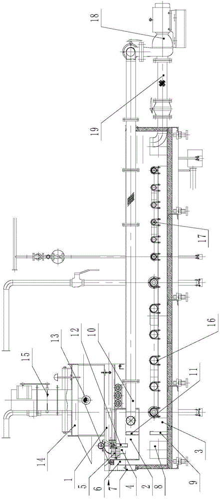
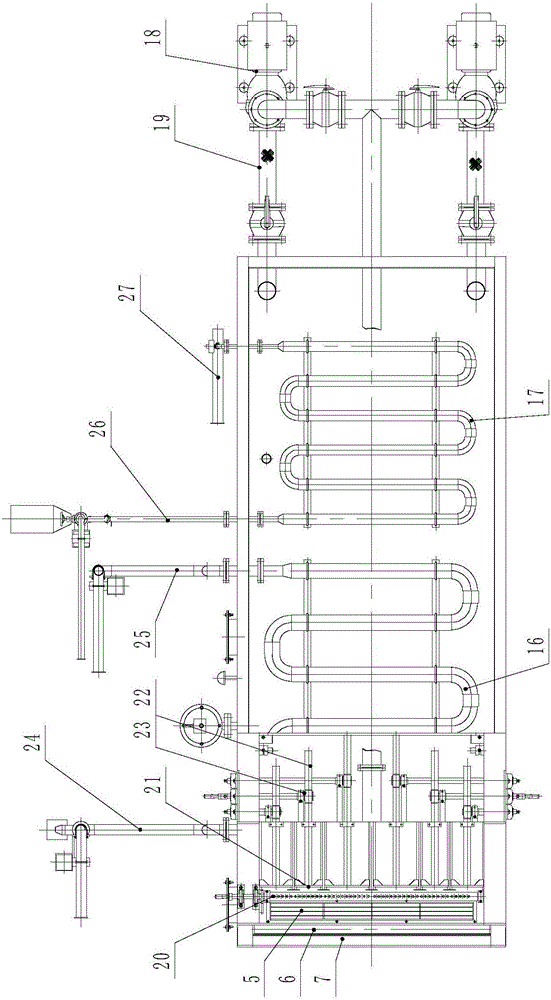
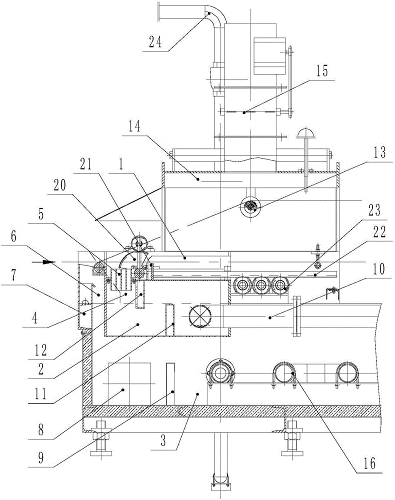
[0030] Such as Figure 1 to Figure 6 As shown, a steel wire water bath quenching unit includes an upper quenching tank and a liquid storage tank 3 below the upper quenching tank. The upper quenching tank includes a quenching tank 1 at the upper part and a liquid injection tank 2 at the lower part. The upper part of the quenching tank body 1 is provided with a steel wire running channel to facilitate the operation of the steel wire, and the upper part of the quenching tank body 1 is provided with a water bath heat preservation cover 14, and a support rod 31 is fixedly installed on the water bath heat preservation cover 14, and the support rod 31 is rotatably equipped with a mobile hanging wheel 13, which moves and rotates on the support rod 31, and the side doors 30 that can be opened or closed are provided on the sides of the water bath heat preservation shell 14, and the water ...


PUM


Abstract

The invention discloses a water-bath quenching unit for steel wires. The water-bath quenching unit comprises an upper quenching tank and a liquid storage tank, wherein the upper quenching tank comprises a quenching tank body and a liquid injection tank body; a liquid inlet section, a wire separating section, a water bath section and a liquid return section are sequentially arranged on the quenching tank body; the liquid inlet section is provided with a liquid inlet channel; a wire separating comb is horizontally rotationally arranged on the wire separating section; the water bath section is provided with a plurality of water-bath sub-tanks for performing water-bath cooling on the steel wires; a moving baffle is glidingly arranged inside each water-bath sub-tank in the moving direction of the steel wires; each moving baffle is connected with a corresponding baffle adjusting mechanism; and a liquid supply system is arranged between the liquid storage tank and the liquid injection tank body. With the adoption of the water-bath quenching unit, the quenching time and the quenching length can be freely adjusted in a certain range, and various products with different specifications and strength can be produced simultaneously; besides, automatic water addition and automatic temperature control can be realized, so that the steel wires are quenched in the required quenching temperature range all the time, and the quenching effect of the steel wires is improved.

Description

technical field [0001] The invention relates to a steel wire water bath quenching unit, which is used for austempering steel wire. Background technique [0002] Steel wire isothermal water bath and air cooling quenching is a heat treatment process of immersing steel wire in an aqueous solution containing high molecular polymer for continuous rapid cooling, rapid air cooling, air cooling and heat preservation. In order to achieve this purpose, before the steel wire is cooled and quenched in an isothermal water bath and non-isothermal air, the steel wire must first be heated to a state of complete austenite crystal structure and obtain austenite crystal structure with a grain size of 7-8. The purpose of steel wire isothermal water bath and non-isothermal air cooling and quenching is to obtain a sorbite crystal structure with uniform and fine grains, and then obtain higher strength, toughness and good plasticity. After the steel wire is austenitized and heated at high temperat...

Claims


Application Information

Patent Timeline
IPC IPC(8): C21D1/64
CPCC21D1/64
Inventor 马德凡
Owner ZHANGJIAGANG DONGHANG MACHINERY
Why Eureka
Try Eureka