Degassing filter

A filter and air cap technology, applied in the direction of moving filter element filter, filter separation, filter circuit, etc., can solve the problems of filter screen blockage, affecting the rate of filtration, and liquid leakage.

Inactive Publication Date: 2021-06-08
范龙飞
View PDF6 Cites 0 Cited by
  • Summary
  • Abstract
  • Description
  • Claims
  • Application Information

AI Technical Summary

Problems solved by technology

[0003] 1. The existing degassing filter uses liquid to change the flow direction inside the cylinder. Due to the irregularity of the fluid and the change of the flow rate, it is easy to prevent the air inside the liquid from escaping, thus losing the effect of degassing At the same time, when the escaped air inside the degassing filter reaches a certain amount, the air pressure will cause the liquid level to drop and trigger the liquid level switch to deflate. In this way, on the one hand, the air pressure will cause part of the air to be mixed into the liquid again on the other hand. On the one hand, the method of controlling the liquid level switch through the liquid level cannot guarantee the accuracy, and when the flow rate changes, it will also cause different changes in the liquid level, so that accurate deflation cannot be achieved;
[0004] 2. When using the degassing filter to filter the solid impurities in the liquid, since the liquid outlet is located on one side of the cylinder, the filter screen on one side will be seriously blocked when filtering, which is not conducive to the filter screen assembly Long-term use, while not removing the impurities accumulated inside the filter element assembly will affect its filtration rate and reduce the overall efficiency;
[0005] 3. When the degassing filter is in use, due to the sudden increase of the flow rate and flow rate, the overflow will occur. On the one hand, the overflow will cause the liquid to leak out. On the other hand, the normal degassing filter cannot be guaranteed. At the same time, the overflow will also It will make the degassing filter work under negative pressure, affect its service life and cause a certain degree of danger

Method used


Image

  • Degassing filter
  • Degassing filter
  • Degassing filter

Examples


Embodiment Construction

[0024] The following will clearly and completely describe the technical solutions in the embodiments of the present invention with reference to the accompanying drawings in the embodiments of the present invention. Obviously, the described embodiments are only some, not all, embodiments of the present invention. Based on the embodiments of the present invention, all other embodiments obtained by persons of ordinary skill in the art without making creative efforts belong to the protection scope of the present invention.

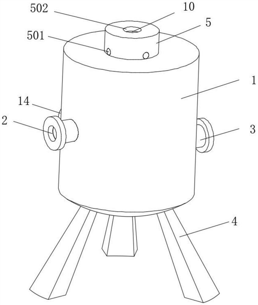
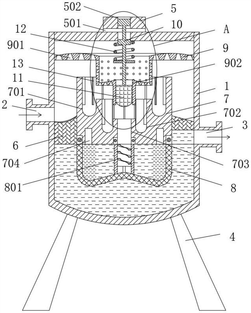
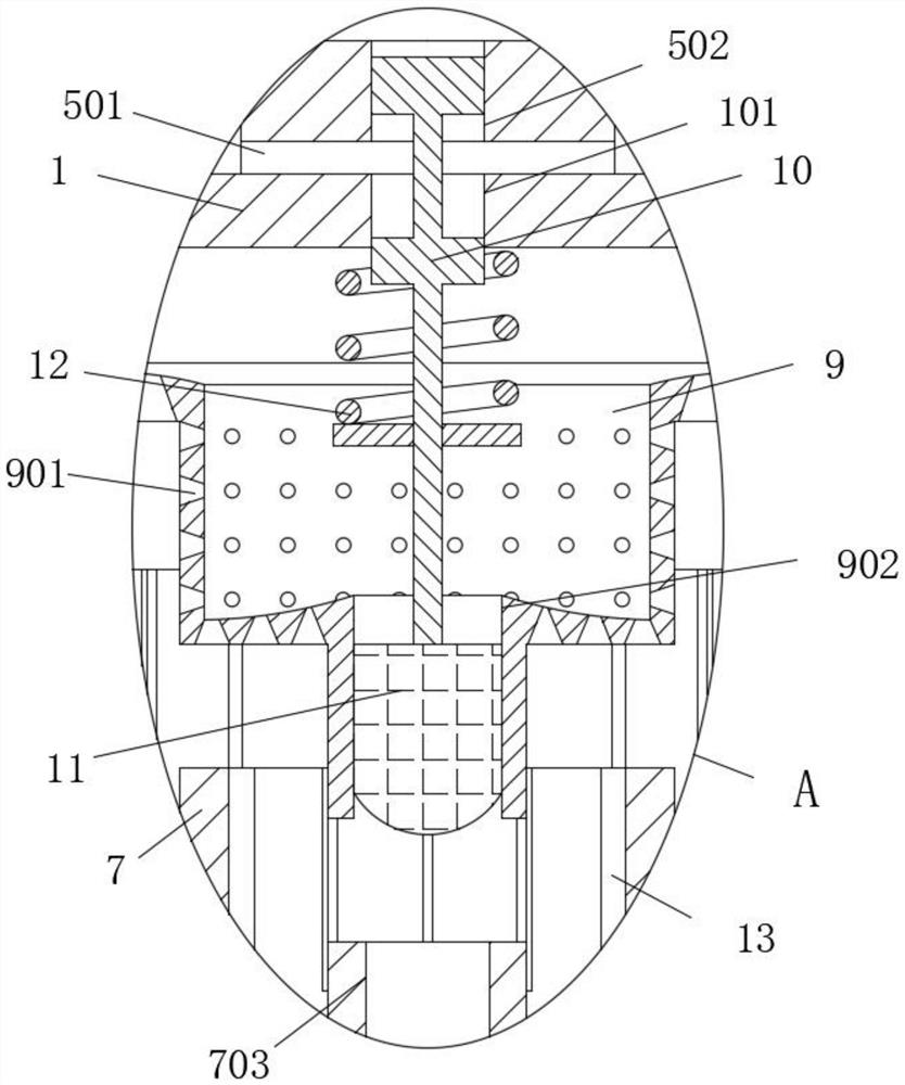
[0025] see Figure 1-5 , a degassing filter, comprising a cylinder 1, a liquid inlet 2 is opened on one side of the cylinder 1, a liquid outlet 3 is opened on the other side of the cylinder 1, and a support 4 is fixedly installed on the bottom of the cylinder 1 , The back of the cylinder 1 is fixed with a sewage suction port 14, the top of the cylinder 1 is fixedly installed with a control air valve 5, and the surrounding of the control air valve 5 is evenly o...


PUM


Abstract

The invention relates to the technical field of filtering equipment, and discloses a degassing filter which comprises a barrel, a dirt suction opening is fixedly formed in the back face of the barrel, a control air valve is fixedly installed at the top of the barrel, a sleeve hole is formed in the middle of the control air valve, an air guide hole communicated with the control air valve and the sleeve hole is formed in the top wall of the barrel, a flow guide ring is fixedly installed on a middle ring in the barrel, a flow guide column is fixedly installed on an inner ring of the flow guide ring, a filter element assembly is movably installed at the bottom of the flow guide column through a bearing, an air cover is fixedly installed at the position, over the flow guide column, in the barrel, a sliding hole is formed in the middle of the air cover, a piston is movably sleeved with the sliding hole, the top of the piston is fixedly connected with an air valve control column, and one end of the air valve control column penetrates through the air guide hole and is connected into the sleeve hole in a sleeved mode. Through the structural design and the function of the flow guide column and the air valve control column, the degassing and filtering effects are improved.

Description

technical field [0001] The invention relates to the technical field of filter equipment, in particular to an air getter filter. Background technique [0002] In order to ensure the accuracy of liquid delivery monitoring, it is generally necessary to process the liquid, including removing air and solid impurities contained in the solution. The commonly used equipment is the degassing filter, which uses the liquid to change the flow direction inside the container to dissolve it. At the same time, the filter assembly is used to filter the solid impurities in the liquid. Its structure is simple but it can achieve the separation of solid, liquid and gas. Therefore, it is widely used, but there are still some problems in actual use. The problem: [0003] 1. The existing degassing filter uses liquid to change the flow direction inside the cylinder. Due to the irregularity of the fluid and the change of the flow rate, it is easy to prevent the air inside the liquid from escaping, t...

Claims


Application Information

Patent Timeline
IPC IPC(8): B01D33/11B01D36/00
CPCB01D33/11B01D36/001
Inventor 不公告发明人
Owner 范龙飞
Why Eureka
Try Eureka