Flame thermal cutting groove head mechanism device

A mechanism device and flame heating technology, applied in the direction of gas flame welding equipment, welding equipment, metal processing equipment, etc., can solve the problems of low production efficiency, inability to adapt to the needs of the thermal cutting industry, and inability to cut

Pending Publication Date: 2021-06-08
昆山乾坤机器制造有限公司
View PDF0 Cites 0 Cited by
  • Summary
  • Abstract
  • Description
  • Claims
  • Application Information

AI Technical Summary

Problems solved by technology

[0004] 1. It can only cut the straight line and curved groove in the same parallel plane as the moving direction, and cannot automatically switch the cutting of the straight line and curved groove edge of the intersecting surface of the cutting and moving direction, and cannot cut the groove on the round pipe;
[0005] 2. All cutting bevel angles need to be manually adjusted before cutting, and the correction angle needs to be adjusted repeatedly. The adjustment process is complicated and the precision is low;
[0006] 3. It is imp...

Method used


Image

  • Flame thermal cutting groove head mechanism device
  • Flame thermal cutting groove head mechanism device

Examples


specific Embodiment 1

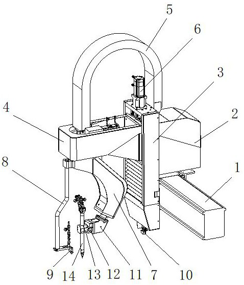
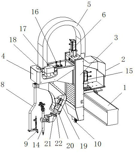
[0031] Specific embodiment one, please refer to Figure 1-2 , a flame thermal cutting bevel head mechanism device, comprising a gantry beam 1, a transverse drive body 2 is installed on the gantry beam 1, and a transverse movement servo motor 15 is arranged inside the transverse drive body 2, and the transverse movement The servo motor 15 can drive the horizontal driving body 2 to reciprocate along the gantry beam 1. The vertical driving body 2 is fixed with an up and down lifting body 3, and the top of the up and down lifting body 3 is fixed with a servo motor 6 for moving up and down. The up and down moving servo motor 6 can drive the up and down lift case 4 to reciprocate in the vertical direction in the up and down lift body 3 through a screw rod, and the up and down lift case 4 is provided with a C-axis servo motor 16, a first-stage precision deceleration motor 17 and two-stage precision deceleration toothed disc 18, and the C-axis servo motor 16 can drive the C-axis rotat...


PUM


Abstract

The invention relates to a flame thermal cutting groove head mechanism device, and belongs to the technical field of flame cutting devices. A transverse driving body is installed on a portal frame cross beam of the flame thermal cutting groove head mechanism device, the transverse driving body can be limited along double guide rails on the portal frame cross beam through a transverse moving servo motor to allow reciprocating motion of one degree of freedom, an up-down lifting body is installed on the vertical face of the transverse driving body, an up-down moving servo motor is controlled through a system, an up-down lifting housing, a shaft rotating swing arm and an ignition device are driven to vertically move up and down, and meanwhile various cables, gas pipes, oxygen pipes and the like are arranged inside an engineering plastic tank chain and move up and down along with a lifting body. According to the flame thermal cutting groove head mechanism device, automatic flame groove cutting can be effectively achieved, desired groove parts can be formed through one-time cutting, the operation is easy, a system automatically controls linkage of two shafts on the mechanism, and the X shaft, the Y shaft and the lifting Z shaft on the portal frame do not need to compensate for angle deviation.

Description

technical field [0001] The invention relates to a flame thermal cutting bevel head mechanism device, which belongs to the technical field of flame cutting devices. Background technique [0002] Oxygen cutting uses the high temperature generated during the combustion of iron oxide to cut carbon steel. The gas flame heats the metal temperature at the cutting point to above the ignition point, and then an excessive high-speed oxygen flow is supplied. Excess oxygen can not only ensure the full combustion of gas and iron, but also rely on its own kinetic energy to blow away the combustion waste. When iron burns, it generates extremely high temperature and releases a large amount of heat. Under the impetus of high-speed oxygen flow, it melts the metal in front of it. At the same time, the molten waste produced by the combustion is blown out of the slot by the high-speed gas, and the melted metal burns again. Melt the metal ahead. In this way, the slit is formed, and the purpose...

Claims


Application Information

Patent Timeline
IPC IPC(8): B23K7/00B23K7/10
CPCB23K7/00B23K7/10
Inventor 李红林曹大洋
Owner 昆山乾坤机器制造有限公司
Why Eureka
Try Eureka