
Automatic discharging device for die

A mold and blanking technology, which is applied in the field of blanking device for mold automation, can solve the problem of inability to replace molds, and achieve the effect of convenient and quick replacement of static molds and stable and powerful functions.

Active Publication Date: 2021-06-08
宜宾综合保税区供应链管理有限公司
View PDF13 Cites 0 Cited by
  • Summary
  • Abstract
  • Description
  • Claims
  • Application Information

AI Technical Summary

Problems solved by technology

[0002] In the mold blanking process in the prior art, the raw material is injected into the molding cavity of the mold through the feeding pipe to realize the work of feeding the material. In the traditional technology, the feeding pipe is directly fixed on the mold. This method cannot realize fast The replacement mold needs

Method used

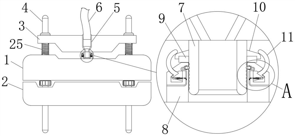
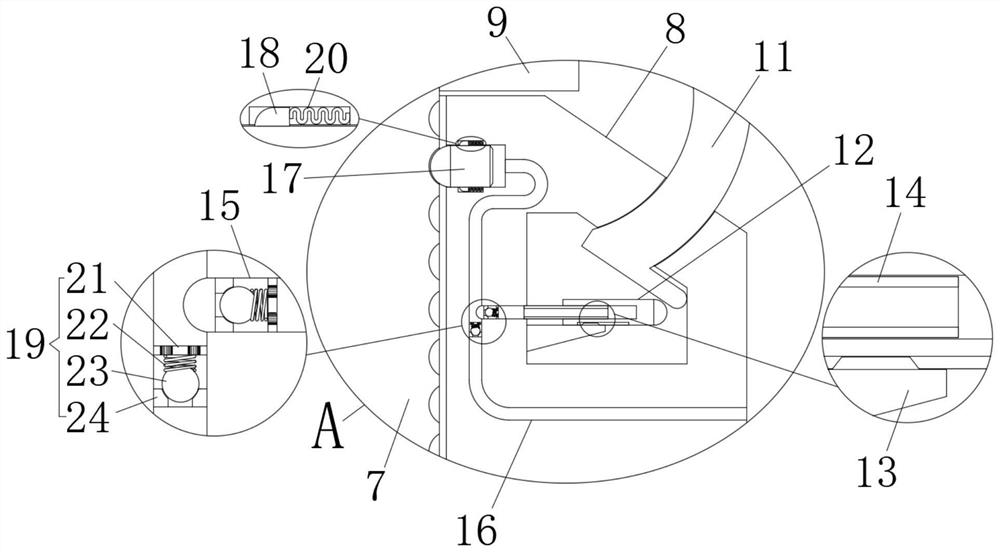
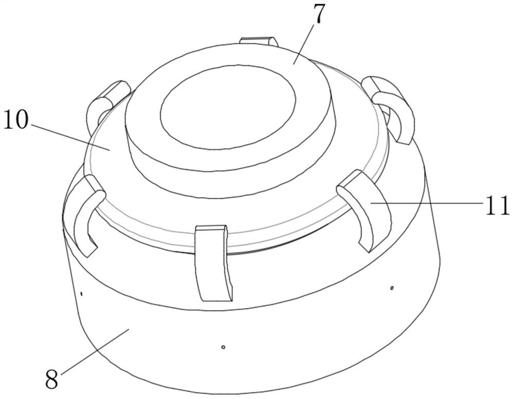

Image

  • Automatic discharging device for die
  • Automatic discharging device for die
  • Automatic discharging device for die

Examples


Embodiment Construction

[0018] The following will clearly and completely describe the technical solutions in the embodiments of the present invention with reference to the accompanying drawings in the embodiments of the present invention. Obviously, the described embodiments are only some, not all, embodiments of the present invention. Based on the technical solutions in the present invention, all other embodiments obtained by persons of ordinary skill in the art without making creative efforts belong to the protection scope of the present invention.

[0019] see Figure 1 to Figure 3 , the present invention provides a technical solution: a mold automatic blanking device, including a static mold 1, a moving mold 2, a control panel 3 and a guide rod 4, the lower end of the static mold 1 is provided with a moving mold 2, and the bottom of the static mold 1 The upper end is provided with a control board 3, two symmetrically distributed guide rods 4 run through the static mold 1, the guide rods 4 respect...


PUM


Abstract

The invention relates to the technical field of discharging devices, in particular to an automatic discharging device for a die. The automatic discharging device comprises a static die, a movable die, a control plate and guide rods; the movable die is arranged at the lower end of the static die, the control plate is arranged at the upper end of the static die, the two symmetrically-distributed guide rods penetrate through the static die, the guide rods penetrate through the movable die and the control plate correspondingly, a control cylinder is embedded in the control panel, the upper end of the control cylinder is fixedly connected with a hose, and the control cylinder penetrates through the control panel. According to the structural design, when raw materials are conveyed on the hose, impact force drives the control panel to descend, then an inner barrel is inserted into an outer barrel, meanwhile, a rubber ring achieves the firm sealing effect, the situation that the raw materials overflow from a gap between the outer barrel and the inner barrel is effectively avoided, and automatic control transmission is achieved.

Description

technical field [0001] The invention relates to the technical field of unloading devices, in particular to an automatic unloading device for molds. Background technique [0002] In the mold blanking process in the prior art, the raw material is injected into the molding cavity of the mold through the feeding pipe to realize the work of feeding the material. In the traditional technology, the feeding pipe is directly fixed on the mold. This method cannot realize fast The replacement mold needs. [0003] If we can invent a feeding device, during the feeding process, the feeding pipe is directly fixed on the mold, and after the injection is stopped, the feeding mechanism and the mold are automatically separated, and the problem can be solved. For this reason, we provide a Unloading device for mold automation. Contents of the invention [0004] The object of the present invention is to provide an automated mold blanking device to solve the problems raised in the above-mentio...

Claims


Application Information

Patent Timeline
Patent Type & Authority Applications(China)
IPC IPC(8): B29C31/04
CPCB29C31/04
Inventor 金江涛
Owner 宜宾综合保税区供应链管理有限公司
Learn More