Optical fiber color ring printing positioning device and printing device

A fiber positioning and positioning device technology, applied in printing devices, power transmission devices, printing, etc., can solve problems such as difficulties in installing optical fibers, achieve the effects of reducing tremor, extending contact area, and improving applicability

Active Publication Date: 2021-06-08
德阳汇川科技有限公司
View PDF10 Cites 0 Cited by
  • Summary
  • Abstract
  • Description
  • Claims
  • Application Information

AI Technical Summary

Problems solved by technology

[0004] The purpose of the present invention is to provide an optical fiber color ring printing and positioning device and printing device to solve the problem of difficult installation of optical fiber in the prior art

Method used


Image

  • Optical fiber color ring printing positioning device and printing device
  • Optical fiber color ring printing positioning device and printing device
  • Optical fiber color ring printing positioning device and printing device

Examples


Embodiment

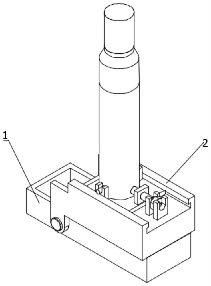
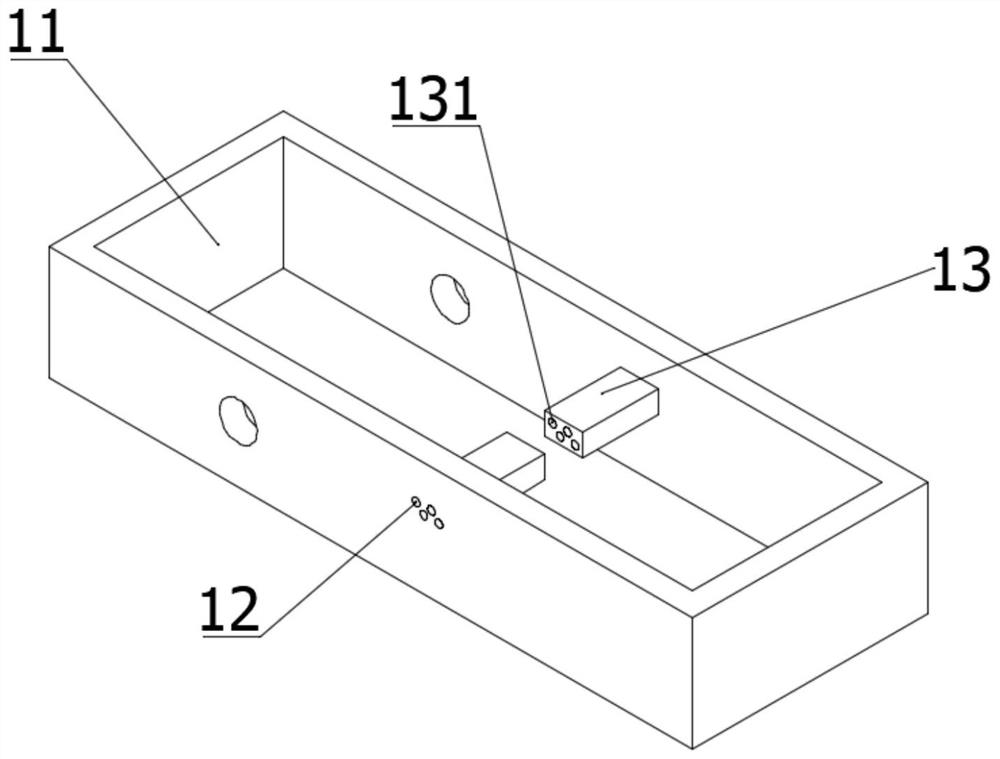
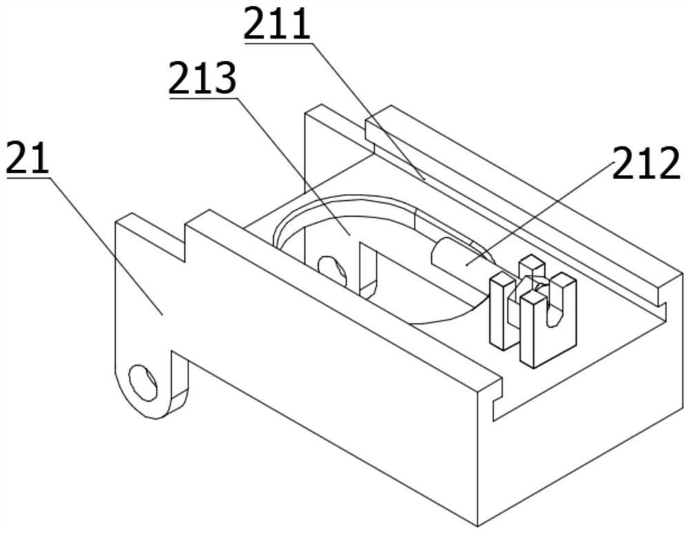
[0054] Such as Figure 1-Figure 2 As shown, the embodiment of the present application provides an optical fiber color ring printing positioning device, including an optical fiber positioning module 1 and a nozzle positioning module 2; the optical fiber positioning module 1 includes a cavity, and two The side wall is provided with a first through hole 12 for the optical fiber to pass through; the nozzle positioning module 2 is hinged to the optical fiber positioning module 1; the nozzle positioning module 2 rotates along the hinged position to realize the sealing of the cavity.

[0055] Preferably, a guide is provided on the side wall where the optical fiber enters the first through hole 12 , and the optical fiber is guided into the first through hole 12 through the guide.

[0056] Preferably, the contact surface between the guide and the pipeline is arc-shaped, and the arc-shaped structure reduces the friction between the surface of the optical fiber and the contact position w...


PUM


Abstract

The invention discloses an optical fiber color ring printing positioning device which comprises an optical fiber positioning module and a spray head positioning module, wherein the optical fiber positioning module comprises a cavity, and first through holes through which optical fibers can pass are formed in two opposite side walls of the cavity; the spray head positioning module is hinged with the optical fiber positioning module; and the spray head positioning module rotates along the hinged position to realize the closing of the cavity. The n optical fiber color ring printing positioning device is simple in structure, closing and opening of the cavity of the optical fiber positioning module are achieved through structural design, and the problem that in the prior art, optical fibers are difficult to install before printing is solved.

Description

technical field [0001] The invention relates to the technical field of optical fiber production, in particular to an optical fiber color ring printing positioning device and a printing device. Background technique [0002] Communication optical cables generally contain multiple optical fibers. In order to facilitate the identification of optical fibers during the production process of the optical cable and during the use of the optical cable, the optical fibers should be painted with bright, smooth, stable and reliable colors before the production of the optical cable. [0003] In the coloring process of the existing optical fiber color ring, the optical fiber needs to be threaded into the corresponding coloring module. Due to the lack of visible space and operable space, the threading is difficult, and the position of the corresponding coloring module will be affected after the threading , thereby affecting the shading quality. Contents of the invention [0004] The purp...

Claims


Application Information

Patent Timeline
Patent Type & Authority Applications(China)
IPC IPC(8): B41J3/407B41J11/00B41J25/24B41J29/38
CPCB41J3/4073B41J11/0045B41J25/24B41J29/38
Inventor 陈曲陈天才黎明杨卫东黄骏刘圣怀
Owner 德阳汇川科技有限公司
Why Eureka
Try Eureka