Lamp body

A technology of lamp body and light guide body, which is applied in the directions of road vehicles, vehicle parts, lighting and heating equipment, etc., to achieve the effect of suppressing large-scale

Active Publication Date: 2021-06-08
HONDA MOTOR CO LTD
View PDF6 Cites 0 Cited by
  • Summary
  • Abstract
  • Description
  • Claims
  • Application Information

AI Technical Summary

Problems solved by technology

[0005] However, in the technique described in Patent Document 1, there is still room for improvement in expressing a further sense of depth.

Method used


Image

  • Lamp body
  • Lamp body
  • Lamp body

Examples


no. 1 approach

[0056] (lamp body)

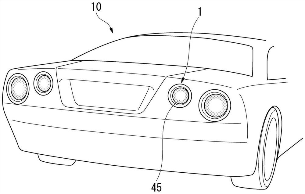
[0057] figure 1 It is a perspective view of a vehicle 10 mounted with the lamp body 1 according to the first embodiment viewed from the rear.

[0058] The lamp body 1 is suitable for, for example, a tail lamp or a stop lamp provided at the rear end of the vehicle 10 . The lamp body 1 emits light toward the rear of the vehicle 10 .

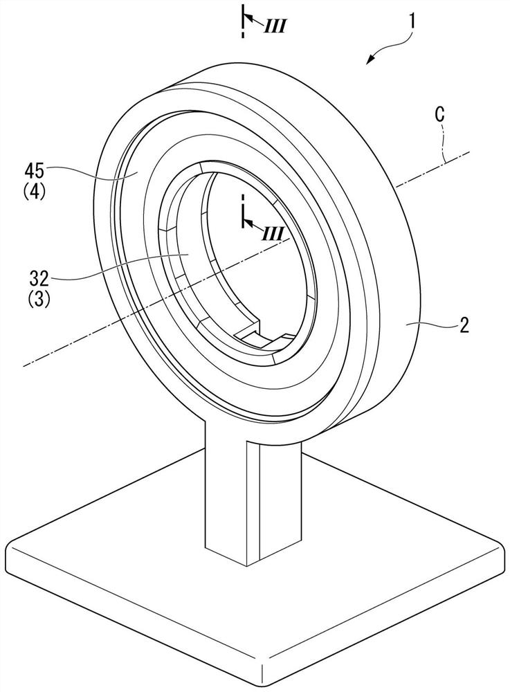
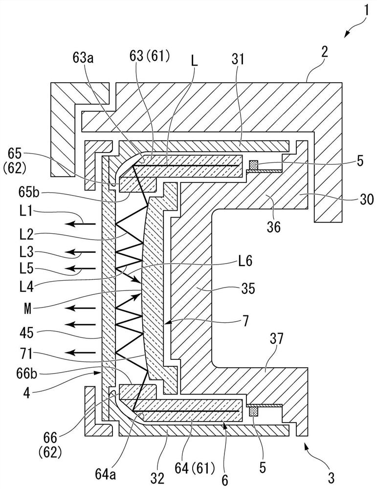
[0059] figure 2 It is an external perspective view of the lamp body 1 of the first embodiment. image 3 is along figure 2 A cross-sectional view of the lamp body 1 along line III-III.

[0060] Such as figure 2 As shown, the lamp body 1 is formed in a ring shape centered on an axis C along the front-rear direction of the vehicle 10 . In the following description, sometimes the direction along the axis C of the lamp body 1 is simply called the axial direction, the direction perpendicular to the axis C is called the radial direction, and the direction around the axis C is called the circumferential direction. The irradi...


PUM


Abstract

The invention provides a lamp body which can restrain enlargement and can further show the sense of depth. The lamp body includes a light source (5), a light guide body (6) configured to cause light (L) from the light source to be guided and cause the light to be emitted from a light emitting surface (45), a reflector (7) configured to cause the light, which has exited from a light guide exit surface (65b, 66b) of the light guide body, to be reflected toward a side of the light emitting surface; and a half mirror (4) disposed to face the reflector (7) and having a reflection area where the light (L) reflected by the reflector (7) is reflected toward a side of the reflector and a transmission area where the reflected light is transmitted. The light guide body (6) has: a first light guide lens (61) that guides light (L) from the light source (5) in a first direction; and a second light guide lens (62) having a light guide emission surface for emitting light (L) in a second direction intersecting the first direction, the first light guide lens and the second light guide lens being disposed in a state of being in contact with each other.

Description

technical field [0001] The invention relates to a lamp body. Background technique [0002] Conventionally, in lamp bodies for vehicles such as tail lamps, a structure in which a light source and a light guide are combined is known. In these lamp bodies, in order to express a sense of depth while reducing the thickness, various techniques have been proposed to make the light from the light emitting surface appear three-dimensional by reflecting the light from the light source multiple times inside. [0003] For example, Patent Document 1 (Japanese Unexamined Patent Publication No. 2017-92010) discloses a structure of a light guide having a light guide that emits a part of light from a light source in one direction. A light exit surface; a light guide incident surface for the light emitted from the light guide exit surface; and a light guide reflective surface that reflects another part of the light from the light source or the light incident from the light guide incident sur...

Claims


Application Information

Patent Timeline
Patent Type & Authority Applications(China)
IPC IPC(8): F21S43/235F21S43/247F21S43/30F21W103/00F21W107/10
CPCF21S43/235F21S43/30F21S43/247F21W2103/00F21W2107/10F21S43/40F21S43/31F21S43/251F21S43/239F21S43/245F21S43/33F21S43/315F21S43/37
Inventor 槌谷裕志中岛大介岩尾俊介田古里真嘉
Owner HONDA MOTOR CO LTD
Why Eureka
Try Eureka