Wireless charger capable of rapidly dissipating heat

A wireless charger and charger technology, which is applied in the direction of collectors, electric vehicles, electrical components, etc., can solve the problems of reducing normal working efficiency, difficult to popularize and apply, and difficult to quickly dissipate heat of wireless chargers.

Pending Publication Date: 2021-06-08
深圳市伟博新智能科技有限公司
View PDF6 Cites 0 Cited by
  • Summary
  • Abstract
  • Description
  • Claims
  • Application Information

AI Technical Summary

Problems solved by technology

[0003] Although the current wireless charger can wirelessly charge the mobile phone, during the charging process of the mobile phone, a large amount of heat will be generated inside the wireless charger. The long-term high temperature of electrical components will affect their service life and reduce their normal working efficiency. It can be seen from the above that the existing wireless chargers have the disadvantage of being difficult to dissipate heat quickly, and it is difficult to be popularized and applied.

Method used


Image

  • Wireless charger capable of rapidly dissipating heat
  • Wireless charger capable of rapidly dissipating heat
  • Wireless charger capable of rapidly dissipating heat

Examples


Embodiment 1

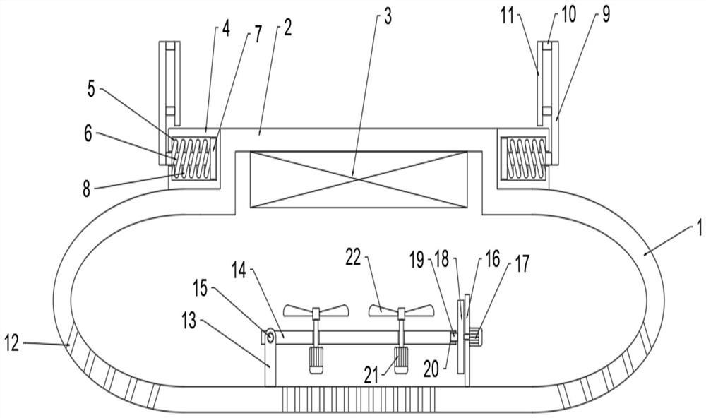
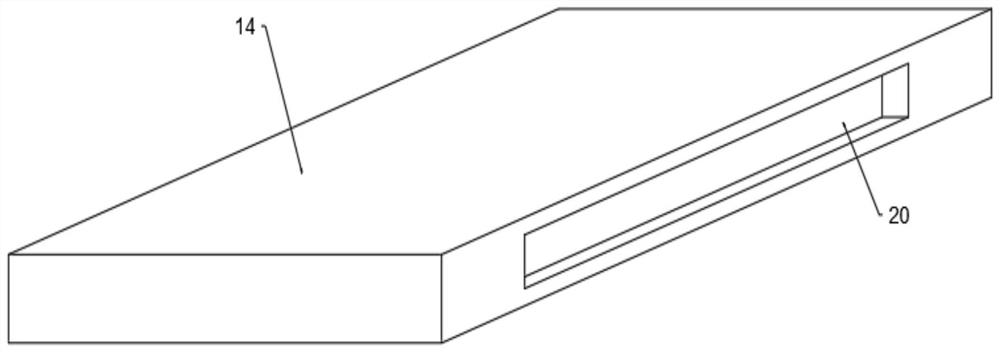
[0022] Example 1 see Figure 1 ~ Figure 2 , the present invention provides a fast heat dissipation wireless charger, comprising a charger shell 1, a charging platform 2 is provided on the upper part of the charger shell 1, and a wireless charging device is fixedly installed inside the charger shell 1 below the charging platform 2 3. The side boxes 4 are fixedly installed on both sides of the charging platform 2, and the inside of the side box 4 is provided with fixed components. The bottom and side walls of the charger shell 1 are uniformly provided with several air holes 12. The charging The inside of the device housing 1 is provided with a heat dissipation assembly.

[0023] The fixed assembly includes a fixed groove 5, a cross bar 6, a retaining ring 7, a fixed spring 8, a vertical rod 9, a connecting block 10 and a baffle plate 11, and the inside of the side box 4 is provided with a fixed groove 5, and the fixed groove 5 The inside is slidably provided with a retaining ri...

Embodiment 2

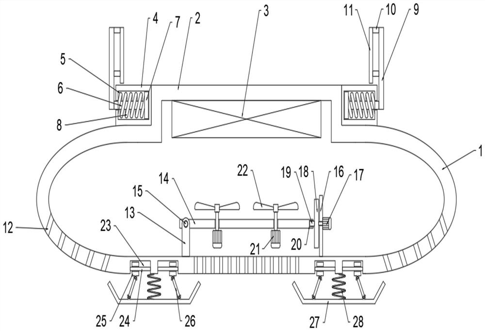
[0028] see Figure 1 ~ Figure 3 , such as a wireless charger with rapid heat dissipation in Embodiment 1, comprising a charger case 1, a charging platform 2 is provided on the top of the charger case 1, and a charging platform 2 is fixed inside the charger case 1 below the charging platform 2. Wireless charging device 3, side boxes 4 are fixedly installed on both sides of the charging platform 2, fixed components are arranged inside the side box 4, and several ventilation holes 12 are uniformly arranged on the bottom and side walls of the charger shell 1, The charger shell 1 is provided with a cooling assembly inside.

[0029] The difference from Embodiment 1 is that the bottom of the charger housing 1 is symmetrically provided with a shock absorbing assembly, and the shock absorbing assembly includes a mounting groove 23, a sliding rod 24, a sliding block 25, a connecting rod 26, a bottom plate 27 and a shock absorbing spring 28. The bottom of the charger shell 1 is symmetri...


PUM


Abstract

The invention discloses a wireless charger capable of rapidly dissipating heat, belonging to the technical field of mobile phone accessories. The invention aims to solve the problem that an existing wireless charger is difficult to rapidly dissipate heat. The wireless charger is technically characterized in that the wireless charger comprises a charger shell, wherein a charging platform is arranged on the upper portion of the charger shell; a wireless charging device is fixedly installed in the charger shell below the charging platform; side boxes are fixedly installed on the two sides of the charging platform; fixing assemblies are arranged in the side boxes; a plurality of air holes are evenly formed in the bottom and the side walls of the charger shell; a heat dissipation assembly is arranged in the charger shell; and damping assemblies are symmetrically arranged at the bottom of the charger shell. The wireless charger has the advantages of wireless charging, stable fixation, rapid heat dissipation, buffering and damping, simplicity, convenience and practicability.

Description

technical field [0001] The invention relates to the technical field of mobile phone accessories, in particular to a wireless charger for rapid heat dissipation. Background technique [0002] A wireless charger refers to a charger that is connected to a terminal device that needs to be charged without a traditional charging power cord. It adopts the latest wireless charging technology. By using the magnetic field generated between the coils, it can magically transmit electric energy. Inductive coupling technology will Become a bridge connecting charging base stations and equipment. [0003] Although the current wireless charger can wirelessly charge the mobile phone, during the charging process of the mobile phone, a large amount of heat will be generated inside the wireless charger. Long-term exposure to high temperature of electrical components will affect their service life and reduce their normal working efficiency. It can be seen from the above that the existing wireles...

Claims


Application Information

Patent Timeline
IPC IPC(8): H02J50/00H02J7/00H04M1/04F16F15/067H05K7/20
CPCH02J50/001H02J7/0044H04M1/04F16F15/067H05K7/20136
Inventor 李军
Owner 深圳市伟博新智能科技有限公司
Why Eureka
Try Eureka