Micro humidifier

A humidifier and miniature technology, applied in respirator and other directions, can solve the problems of increasing the amount of energy, increasing the complexity of the system, etc., to achieve the effect of reducing energy requirements, reducing treatment complications and costs, and reducing growth

Inactive Publication Date: 2021-06-11
陈峰
View PDF0 Cites 0 Cited by
  • Summary
  • Abstract
  • Description
  • Claims
  • Application Information

AI Technical Summary

Problems solved by technology

Such an arrangement also increases the complexity of the system and increases the amount of energy required to provide acceptable heated moist air for the patient to breathe

Method used


Image

  • Micro humidifier
  • Micro humidifier
  • Micro humidifier

Examples


Embodiment Construction

[0020] Unless otherwise specified, all tests herein were performed under standard conditions, including a laboratory and test temperature of 25°C, a pressure at sea level (1 atmosphere), and a pH of 7, and all measurements were made at Performed in metric units. In addition, all percentages, ratios, etc. herein are by weight unless otherwise specified.

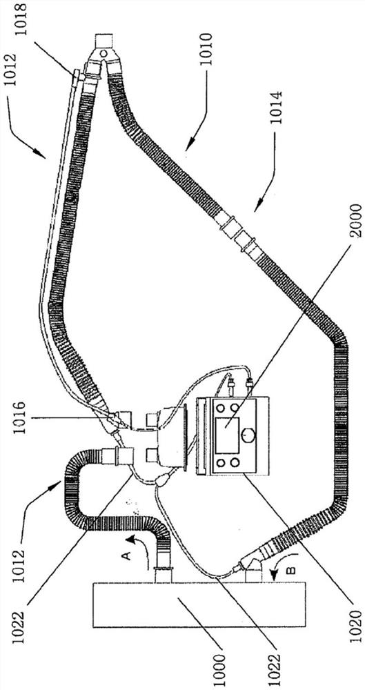
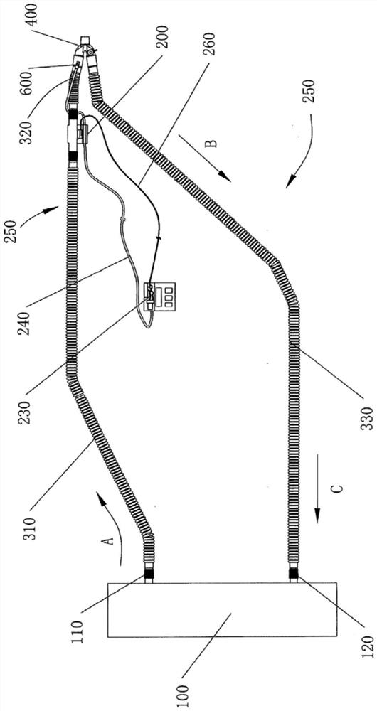
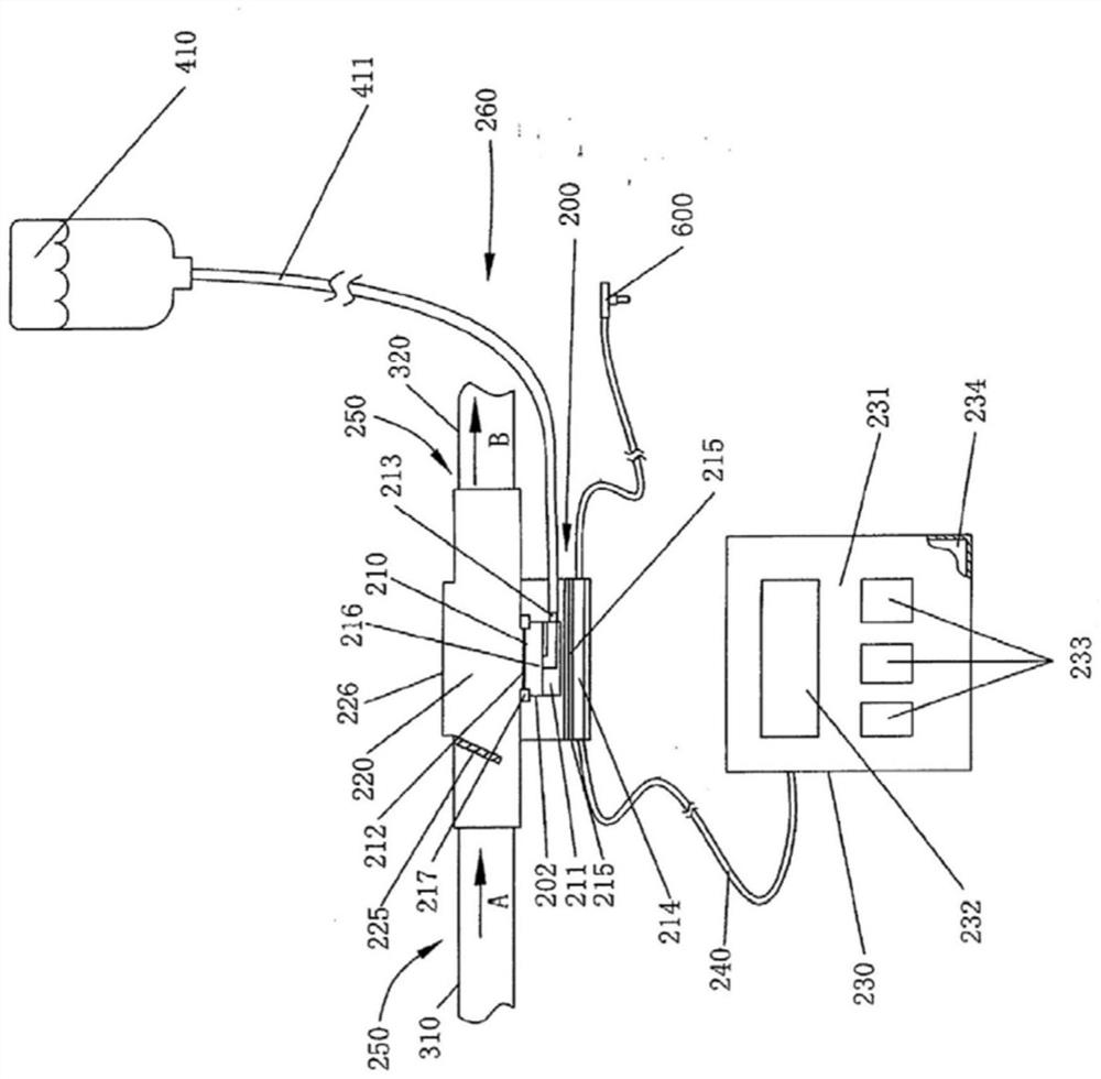
[0021] As used herein, the term "upstream" indicates the direction from which a fluid (eg, air flow, liquid fluid, etc.) flows. In contrast, as used herein, the term "downstream" indicates the direction of fluid flow away. In the drawings herein, air flow is indicated by arrows A, B, and sometimes by arrow C. In these figures, A is always upstream of B, which in turn is upstream of C (when C is present). Conversely, C (when present) is always downstream of B, which in turn is downstream of A. exist Figure 4 In , X is upstream of Y when indicating the direction of fluid flow.

[0022] As used herein, the term "operably c...


PUM


Abstract

The invention relates to a micro humidifier for operably connecting to a breathing circuit, which includes a liquid feed, a liquid chamber operably connected to the liquid feed, and a vapor generator operably connected to the liquid chamber. The liquid chamber has a volume of from about 0.01 ml to about 30 ml. The micro humidifier is operably connected to and/or designed to be operably connected to the breathing circuit upstream of the patient. When the micro humidifier is operably connected to the breathing circuit, steam from the steam generator enters the breathing circuit. A breathing humidifying system comprises a breathing loop and the micro humidifier disclosed by the invention. The micro humidifier is operably connected to the breathing circuit upstream of the patient, and steam from the steam generator enters the breathing circuit.

Description

technical field [0001] Humidifier devices humidify gas, and more specifically, humidify the gas delivered to a patient in the case of mechanical ventilation. Background technique [0002] Humidifiers are often used in conjunction, for example, often with mechanical ventilation systems, to assist patients in need of humidified air to aid their breathing. This may be the case in a hospital or at the patient's home. [0003] With mechanical ventilation systems, in order to prevent excessive irritation and / or damage to the patient's airway that would result in excessive secretions blocking the airway, it is sometimes preferred to deliver to The patient atmosphere should be about 37°C with up to 100% relative humidity. Furthermore, it is believed that appropriately sized water droplets will have a greater chance of depositing within the bronchioles and alveoli. [0004] Furthermore, the pulmonary deposition properties and efficacy of aerosols are believed to depend primarily o...

Claims


Application Information

Patent Timeline
Patent Type & Authority Applications(China)
IPC IPC(8): A61M16/16
CPCA61M16/16A61M16/161
Inventor 陈峰
Owner 陈峰
Why Eureka
Try Eureka