Milling machine flying cutter with adjustable tool geometric angle and milling machine

A milling machine and tool technology, applied in milling machine equipment, milling cutters, manufacturing tools, etc., can solve the problems of inability to adjust the geometric angle of the tool at the same time, reduce the versatility, and make it difficult to give full play to the cutting performance of the tool, so as to improve the processing efficiency and improve the general performance, and the effect of expanding the processing range

Active Publication Date: 2022-06-07
SHANDONG UNIV
View PDF0 Cites 0 Cited by
  • Summary
  • Abstract
  • Description
  • Claims
  • Application Information

AI Technical Summary

Problems solved by technology

[0004] At present, the cutting tools are all installed on the flying cutter head at a certain geometric angle, and it is impossible to realize the simultaneous adjustment of the geometric angles of the cutting tools such as rake angle, relief angle, leading deflection angle, secondary deflection angle and edge inclination angle, so it is difficult to give full play to the cutting edge of the cutting tool. cutting performance
In addition, the existing milling machine flying cutter head can only be installed with a single specific size of the tool holder, which reduces its versatility

Method used


Image

  • Milling machine flying cutter with adjustable tool geometric angle and milling machine
  • Milling machine flying cutter with adjustable tool geometric angle and milling machine
  • Milling machine flying cutter with adjustable tool geometric angle and milling machine

Examples


Embodiment 1

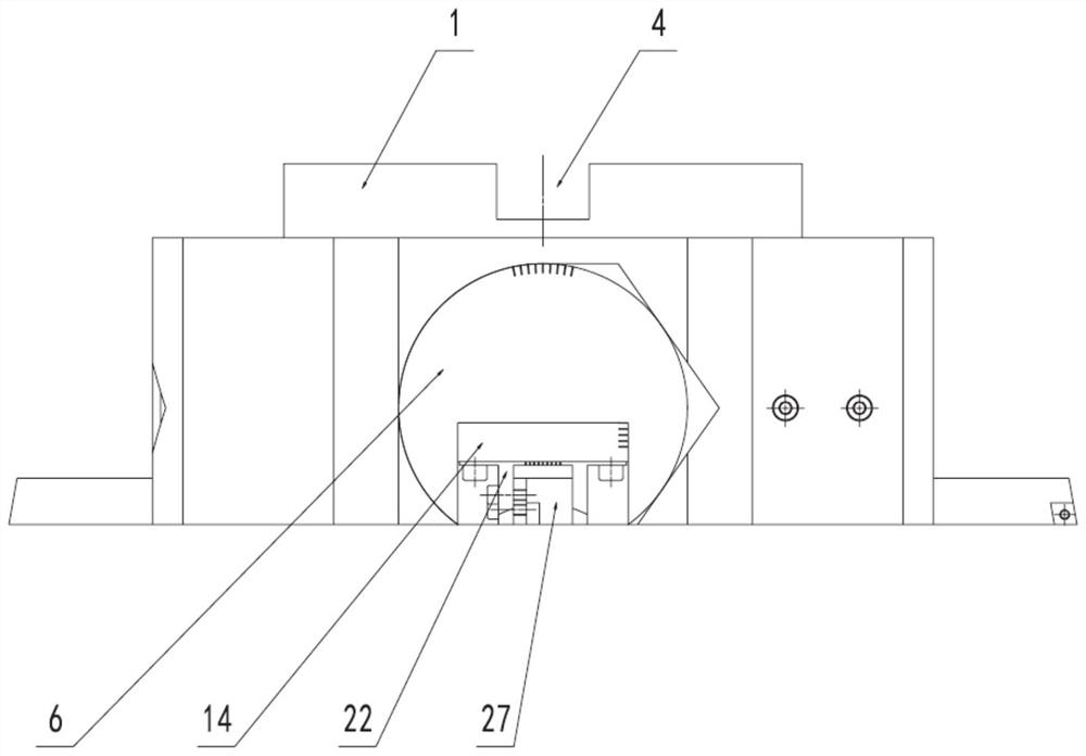
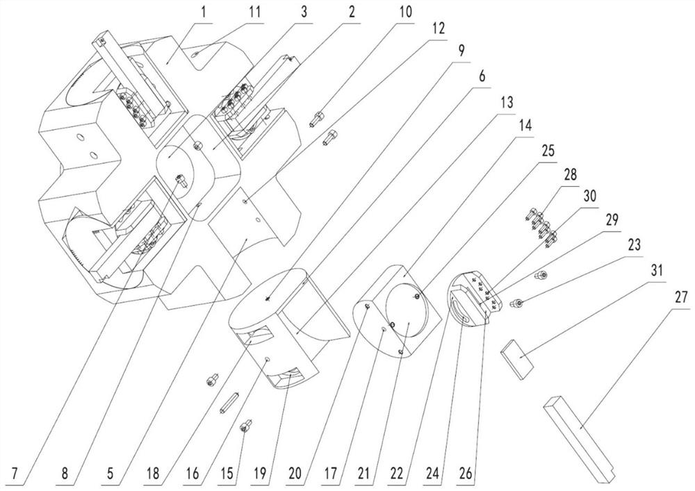
[0035] This embodiment provides a milling machine flying cutter with adjustable cutter geometry angle, such as figure 1 and figure 2 As shown in the figure, it includes a flying cutter head body 1, an adjustment assembly and a cutter bar 27. The flying cutter head body 1 is evenly spaced circumferentially to install a plurality of adjustment assemblies, and the cutter bar 27 is connected with the adjustment assembly. Angle, clearance angle, main declination angle, secondary declination angle and edge inclination angle adjustment, and can adapt to different sizes and specifications of the arbor 27.

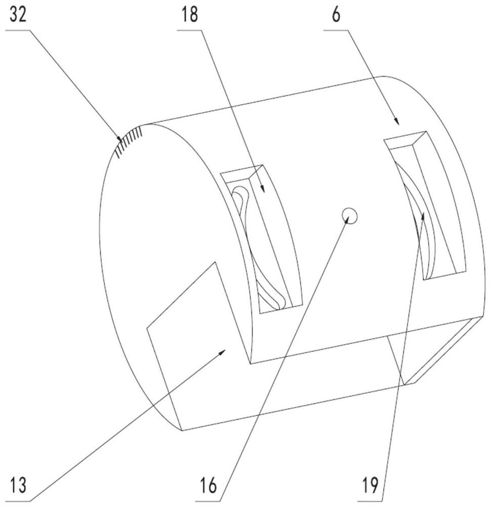
[0036] Further, the adjustment assembly includes front and rear angle adjustment blocks 6, main and auxiliary declination angle adjustment blocks 14, and edge inclination angle adjustment blocks 22. The block 6 is connected with the flying cutter disc body 1 .

[0037] Specifically, the bottom end face of the flying cutter head body 1 (with the orientation of the flying cutter a...

Embodiment 2

[0060] This embodiment provides a milling machine, including the milling machine flying cutter described in Embodiment 1, and the milling machine flying cutter is connected to the milling machine spindle.


PUM


Abstract

The invention discloses a milling machine flying cutter with adjustable cutter geometric angle and a milling machine. The technical proposal is as follows: a flying cutter disc body is provided, and a plurality of combined grooves are evenly opened in the circumferential direction of the flying cutter disc body, and adjustment components are installed in the combined grooves; , the adjustment assembly includes a front and rear angle adjustment block, a main and auxiliary deflection angle adjustment block, and a blade inclination angle adjustment block. One side of the blade inclination angle adjustment block is adsorbed with a knife rod, and the other side is connected to the front and rear angle adjustment block through the main and auxiliary deflection angle adjustment blocks. . The invention can adjust the geometric angle of the tool including the rake angle, the rear angle, the main deflection angle, the secondary deflection angle and the edge inclination angle, and can adapt to various tool holders with different sizes and specifications.

Description

technical field [0001] The invention relates to the field of cutting tools, in particular to a milling machine flying cutter and a milling machine with adjustable tool geometric angle. Background technique [0002] A milling machine is a machine tool that mainly uses milling cutters to process workpieces. The milling cutter is a single-tooth or multi-tooth rotary tool used in milling. During milling, the rotation of the milling cutter is the main movement, and the movement of the workpiece or the milling cutter is the feed movement, so that each tooth of the milling cutter intermittently removes the machining allowance of the workpiece. Milling machines have a wide range of processes, and various planes (horizontal, vertical or inclined surfaces), grooves (keyways, T-slots, helical grooves, etc.), toothed parts and helical surfaces can be processed on the milling machine. The milling machine uses a multi-blade tool for intermittent cutting, high cutting speed, and can mill...

Claims


Application Information

Patent Timeline
Patent Type & Authority Patents(China)
IPC IPC(8): B23C5/26B23C5/08
CPCB23C5/26B23C5/08B23C2210/0407B23C2210/54
Inventor 黄传真陈震刘含莲朱洪涛邹斌姚鹏王军
Owner SHANDONG UNIV
Why Eureka
Try Eureka