
Glass fiber slitting equipment capable of adjusting cutting width

A cutting width, adjustable technology, used in metal processing and other directions, can solve problems such as low work efficiency

Active Publication Date: 2021-06-11
元源新材料有限公司
View PDF20 Cites 2 Cited by
  • Summary
  • Abstract
  • Description
  • Claims
  • Application Information

AI Technical Summary

Problems solved by technology

[0005] In order to overcome the shortcomings of manual cutting one by one and low work efficiency, the technical problem is to provide a glass fiber cutting equipment capable of automatic cutting and high work efficiency with adjustable cutting width

Method used


Image

  • Glass fiber slitting equipment capable of adjusting cutting width
  • Glass fiber slitting equipment capable of adjusting cutting width
  • Glass fiber slitting equipment capable of adjusting cutting width

Examples


Embodiment 1

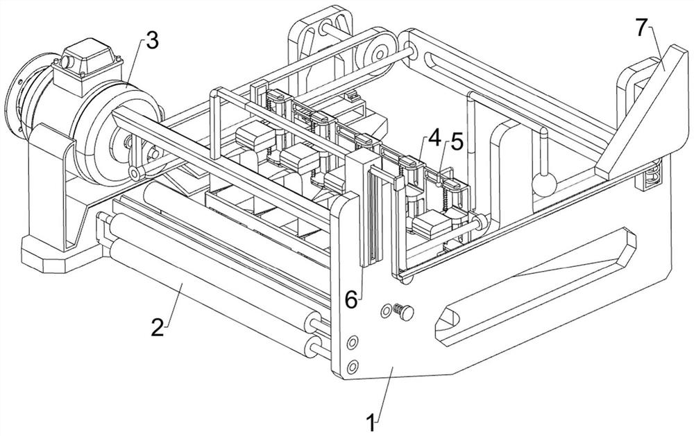
[0022] A glass fiber cutting equipment with adjustable cutting width, such as Figure 1-5 As shown, it includes a first fixed frame 1, a cutting assembly 2, a transmission assembly 3, and a clamping assembly 4. The first fixed frame 1 is provided with a cutting assembly 2, and the first fixed frame 1 is provided with a transmission device through rotation. The transmission assembly 3 is provided on the first fixed frame 1 with a clamping assembly 4 for clamping by sliding.

[0023] When using this device, the staff puts the glass fiber that needs to be cut into the cutting assembly 2, and after putting it in place, clamps the glass fiber through the clamping assembly 4, and after clamping, drives the clamping assembly through the transmission assembly 3 4 moves, and then drives the glass fiber to move, and the glass fiber is cut by the cutting assembly 2 while moving.

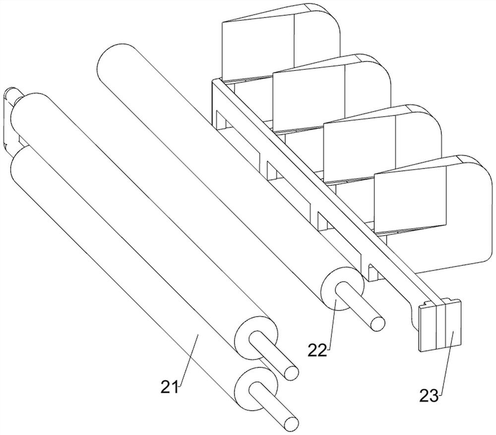
[0024] Such as figure 1 with figure 2 As shown, the cutting assembly 2 includes a first guide cylinder 2...

Embodiment 2

[0031] On the basis of Example 1, such as figure 1 with Figure 4 As shown, a pull assembly 5 is also included, and the pull assembly 5 includes a moving rod 51, a second spring 52, a push frame 53, a first wedge block 54 and a first contact rod 55, and the front part of the first fixed frame 1 is slidingly designed. There are two moving rods 51, a second spring 52 is wound between the moving rods 51 and the first fixed frame 1, a pushing frame 53 is arranged between the two moving rods 51, and the pull plates 45 cooperate with the pushing frame 53, The right part of the pushing frame 53 is provided with a first wedge-shaped block 54 , and the right part of the second fixed frame 42 is provided with a first contact rod 55 , and the first contact rod 55 cooperates with the first wedge-shaped block 54 .

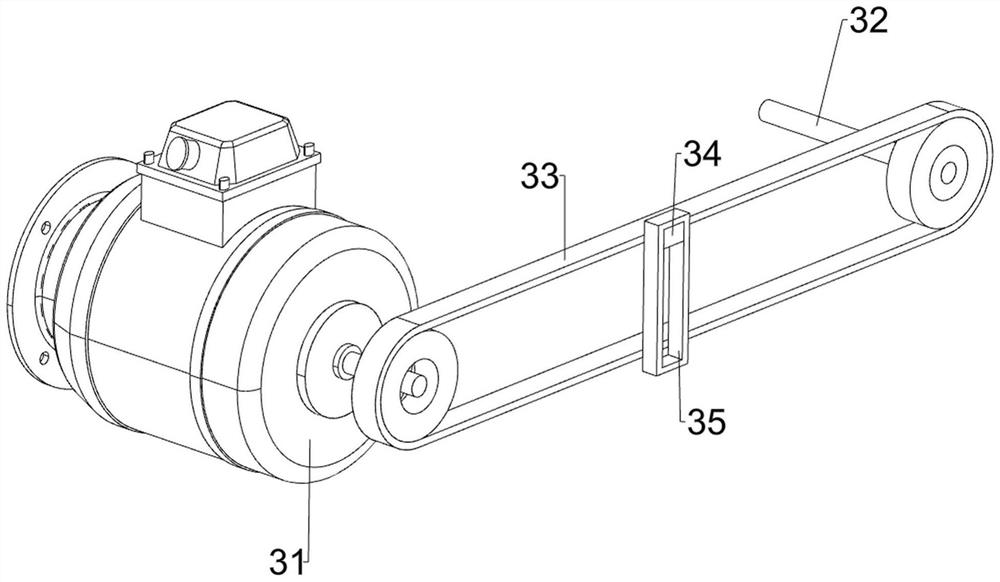
[0032] When the glass fiber is cut, when the pulley set 33 rotates through the fixed block 34 to drive the moving frame 35 to move forward, the second fixed frame 42 drives th...


PUM


Abstract

The invention relates to slitting equipment, in particular to glass fiber slitting equipment capable of adjusting the cutting width. The invention provides the glass fiber slitting equipment capable of adjusting the cutting width, which is capable of automatically cutting glass fibers and high in working efficiency. The glass fiber slitting equipment capable of adjusting the cutting width comprises a first fixing frame, a cutting assembly, a transmission assembly and a clamping assembly. The cutting assembly is mounted on the first fixing frame. The transmission assembly is installed on the first fixing frame and performs transmission in a rotating mode. The clamping assembly is installed on the first fixing frame and conducts clamping in a sliding mode. Glass fibers can be cut through the cutting assembly, power can be provided through the transmission assembly when the glass fibers are cut, the glass fibers can be clamped through the clamping assembly when the glass fibers are cut, clamping blocks can be automatically loosened through a pulling assembly after cutting is completed, and the cut glass fibers can be cut off through a cutting-off assembly.

Description

technical field [0001] The invention relates to a strip cutting device, in particular to a glass fiber strip cutting device with adjustable cutting width. Background technique [0002] Glass fiber is the abbreviation of glass fiber. Glass fiber is an inorganic non-metallic material with excellent performance. Wear resistance is poor. [0003] When glass fiber is used, it needs to be cut into strips according to needs. At present, it is generally cut by manual tools. Cutting in this way needs to be cut one by one, which consumes a lot of time and low work efficiency. [0004] Therefore urgently need to research and develop a kind of can cut automatically, the glass fiber slitting equipment of adjustable cutting width that work efficiency is high is very necessary to solve the above-mentioned problem. Contents of the invention [0005] In order to overcome the shortcomings of manual cutting one by one and low work efficiency, the technical problem is to provide a glass fib...

Claims


Application Information

Patent Timeline
IPC IPC(8): B26D7/02B26D1/08
CPCB26D7/02B26D1/08Y02P40/57
Inventor 张全雷张昭陈伟萍
Owner 元源新材料有限公司
Learn More