Solid rocket engine end socket section inner heat insulation layer pasting device

A sticking device and solid rocket technology, which is applied in the field of sticking devices for the thermal insulation layer in the head section of the solid rocket motor, can solve the problems of inability to realize the precise positioning of the inner thermal insulation layer, low efficiency of the process method, and inseparable manual operation. Hand-rolling and high-complexity operation problems of entering the shell, avoiding the instability of molding quality, and avoiding the effect of high-intensity labor

Active Publication Date: 2021-06-11
XI AN JIAOTONG UNIV
View PDF5 Cites 0 Cited by
  • Summary
  • Abstract
  • Description
  • Claims
  • Application Information

AI Technical Summary

Problems solved by technology

Manual debonding molding inevitably has difficult operations, poor paving quality, and low process efficiency, resulting in a lot of gas and bubbles between layers, and then the quality problem of debonding is prone to occur after the thermal insulation layer is cured, resulting in the rocket working process. , the thermal insulation layer formed by artificial debonding is likely to cause serious problems such as the decline of thermal protection ability, excessive local temperature and even thermal deformation.
[0004] The existing technology for forming the thermal insulation layer in the head section of the solid rocket motor shell still relies on traditional manual debonding molding, or even if the molding process is optimized, it is still inseparable from manual operation, and it is impossible to achieve the inner thermal insulation layer in the molding process. Precise positioning in and guarantee of pasting quality

Method used


Image

  • Solid rocket engine end socket section inner heat insulation layer pasting device
  • Solid rocket engine end socket section inner heat insulation layer pasting device
  • Solid rocket engine end socket section inner heat insulation layer pasting device

Examples


Embodiment Construction

[0047] The present invention will be further described in detail below in conjunction with the accompanying drawings, which are explanations rather than limitations of the present invention.

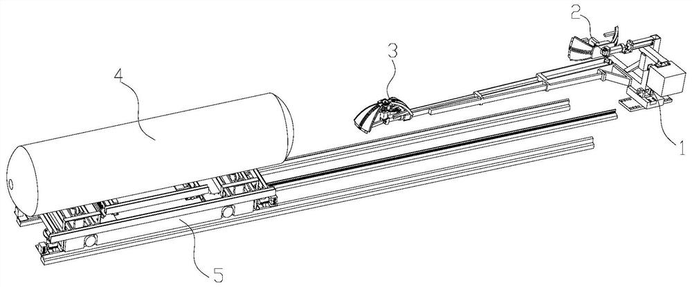
[0048] refer to Figure 1-10 , an automatic pasting system for the thermal insulation layer in the head section of a solid rocket motor, including a pasting unit and an adjustment platform.

[0049] The adjustment platform is arranged on the working path of the pasting unit, the motor housing is placed on the adjustment platform, and the adjustment platform is used to move the motor housing 4 toward the pasting unit.

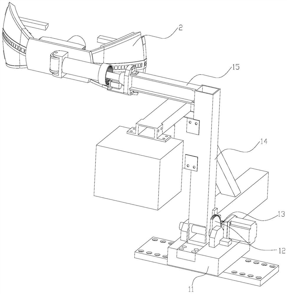
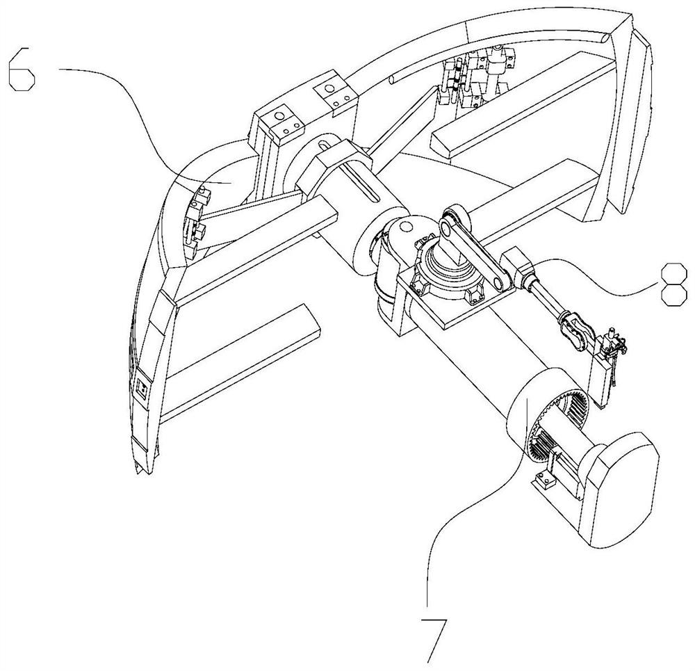
[0050] The pasting unit includes a rotating device 1, a glue spraying robot 8 and two pasting devices.

[0051] Rotating device 1 comprises bracing frame 14 and rotating mechanism and base 11, and bracing frame 14 is installed on the base 11 and is connected with rotating mechanism, and two pasting devices are respectively back pasting device 2 and front pasting device 3,...


PUM


Abstract

The invention discloses a solid rocket engine end socket section inner heat insulation layer pasting device. The device comprises a rotating device and pasting devices, an engine shell is placed on an adjusting platform, the two pasting devices are arranged on the rotating device to conduct heat insulation layer pasting on a rear end socket section and a front end socket section of the engine shell respectively, the two pasting devices enter into working positions in sequence through the rotating device, heat insulation layers are attached to a pasting arm, a pasting angle is controlled through a joint module, the pasting devices can enter into the interior of the engine shell conveniently, pressure is applied to the pasting arm through a lead screw sliding block mechanism, the manual pasting process is simulated, meanwhile, the rotating mechanism rotates according to a set angle, so that the pasting arm rolls and presses all areas of the heat insulation layers, 360-degree rolling and pressing of the heat insulation layers are achieved, the pasting quality of the heat insulation layers is guaranteed, the high-complexity operation problems of manual rolling and entering into the shell by technical workers are solved, the pasting efficiency is improved, and the operation difficulty is reduced.

Description

technical field [0001] The invention relates to the technical field of rocket motor manufacturing, in particular to a device for adhering a thermal insulation layer in a head section of a solid rocket motor. Background technique [0002] The inner heat insulation layer of the solid rocket motor shell includes three parts: the straight line section of the cylinder body, the front head section and the rear head section. The inner heat insulation layer of the solid rocket motor is a thermal protection material located between the inner surface of the shell and the propellant. It can take away most of the heat through its own continuous decomposition and ablation to slow down the propagation speed of the high temperature of the gas to the shell and avoid The engine casing reaches a temperature that endangers its structural integrity in a high-temperature, high-pressure gas environment to ensure the normal operation of the engine. [0003] At present, the head of the metal casin...

Claims


Application Information

Patent Timeline
Patent Type & Authority Applications(China)
IPC IPC(8): B29C65/52
CPCB29C65/522B29C66/80
Inventor 杨培林韩特刘俊陈钢庞宣明陈晓南
Owner XI AN JIAOTONG UNIV
Why Eureka
Try Eureka