
Tire turn-over device

A tire and turning technology, applied in the directions of transportation and packaging, conveyors, mechanical conveyors, etc., can solve the problems of difficulty in lifting tires, unable to keep tires from the state of turning mechanism, etc.

Active Publication Date: 2021-06-11
SHANDONG LINGLONG TIRE +1
View PDF11 Cites 3 Cited by
  • Summary
  • Abstract
  • Description
  • Claims
  • Application Information

AI Technical Summary

Problems solved by technology

[0005] The purpose of the present invention is to provide a tire turning device to solve the technical problems in the prior art that the turning mechanism is difficult to lift the tire and cannot maintain the state when the tire is separated from the turning mechanism

Method used

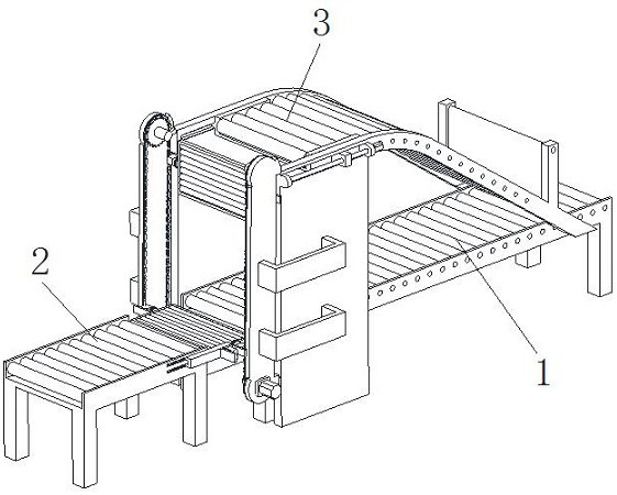
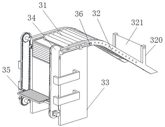
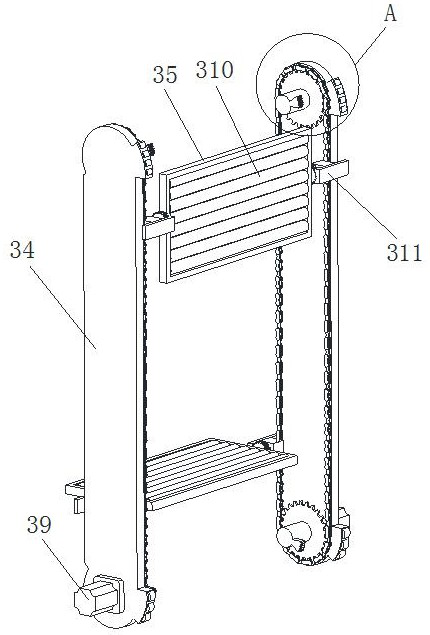

Image

  • Tire turn-over device
  • Tire turn-over device
  • Tire turn-over device

Examples


Embodiment Construction

[0028] The technical solutions of the present invention will be clearly and completely described below in conjunction with the accompanying drawings. Apparently, the described embodiments are some of the embodiments of the present invention, but not all of them.

[0029] The components of the embodiments of the invention generally described and shown in the figures herein may be arranged and designed in a variety of different configurations. Accordingly, the following detailed description of the embodiments of the invention provided in the accompanying drawings is not intended to limit the scope of the claimed invention, but merely represents selected embodiments of the invention.

[0030] Based on the embodiments of the present invention, all other embodiments obtained by persons of ordinary skill in the art without making creative efforts belong to the protection scope of the present invention.

[0031] In the description of the present invention, it should be noted that the t...


PUM


Abstract

The invention discloses a tire turn-over device, and belongs to the technical field of tire production. The device comprises a first conveying belt, conveying equipment and turn-over equipment. During working, a tire is conveyed through conveying equipment, if the tire needs to be turned over, when the tire is conveyed to a bearing plate, a moving motor works to drive a chain to move, at the moment, the bearing plate bearing the tire moves upwards, and at the moment, a second conveying belt moves to the bearing plate; the bearing plate drives the tire to move and turn over, the tire is turned over and placed on the second conveying belt, then the second conveying belt moves to the input end of a third conveying belt, the turned tire is conveyed to the first conveying belt through the third conveying belt, and turning over is achieved; and if the tire conveyed by the conveying equipment does not need to be turned over, the tire is directly conveyed to the first conveying belt through rolling shafts on the bearing plate, and due to the fact that no matter the tire needing to be turned over or the tire not needing to be turned over needs to pass through the bearing plate, it is ensured that the bearing plate can stably lift the tire needing to be turned over.

Description

technical field [0001] The invention relates to the technical field of tire production, in particular to a tire turning device. Background technique [0002] In tire production, it is necessary to print the logo on the positive side of the tire CON. Before printing, it is necessary to turn the tire passing through the roller bed with the positive side of the CON down by 180 degrees so that the positive side of the CON is upward, so that the positive side of the tire CON The ID is printed on the value face. At present, the tire turning method adopted by tire manufacturers is manual turning, which has the disadvantages of wasting manpower, low work efficiency, inaccurate positioning, etc., and cannot meet the needs of automatic tire production. [0003] The invention patent with the publication number of CN109095139B in the prior art discloses a tire turning device, which belongs to the technical field of tire equipment and includes: a transmission roller frame and a turning ...

Claims


Application Information

Patent Timeline
Patent Type & Authority Applications(China)
IPC IPC(8): B65G47/22B65G37/00B65G47/252
CPCB65G37/00B65G47/22B65G47/252B65G2201/0273
Inventor 王锋孙松涛李彦果徐晶孙冰冰马玉静张琦罗洪罡鲁国熹
Owner SHANDONG LINGLONG TIRE
Learn More