Anti-collision buffer guardrail structure for bridge engineering

A technology of bridge engineering and guardrail structure, which is applied in the direction of bridges, bridge construction, bridge parts, etc., can solve the problems of secondary collision, secondary injury, and aggravated accident hazards, so as to ensure the anti-collision buffer performance and facilitate operation and use , the effect of reducing the impact kinetic energy

Active Publication Date: 2021-06-11
中铁十四局集团青岛工程建设有限公司
View PDF5 Cites 1 Cited by
  • Summary
  • Abstract
  • Description
  • Claims
  • Application Information

AI Technical Summary

Problems solved by technology

On ordinary roads or highways, traffic accidents occur frequently due to the excessive speed of vehicles, the most serious of which is that high-speed vehicles hit the guardrails on the side of the road, in the middle of the road or on the side of the bridge, and these guardrails are made of concrete. Bricks are either composed of concrete blocks arranged at intervals and cross rails connecting adjacent blocks, or steel structure cross bars and columns connected. However, these guard rails cannot absorb the impact kinetic energy of the car and are protected after collision. The reverse force of the barrier, the car flips or reverses and deviates from the original lane, and it is very easy to have a secondary collision with the car driving at high speed, causing multiple car crashes and deaths, and aggravating the hazards of the accident.
[0003] For bridges and roads, due to the high safety protection requirements, both sides of the road are generally protected by cement stone piers to prevent vehicles from rushing out of the bridge deck and falling from high altitudes or falling into the water. However, when cement stone piers are used for protection, Since the cement stone pier cannot absorb the impact kinetic energy of the car, it is easy to cause secondary damage in the event of a car accident, and cannot reduce the damage caused by the car accident

Method used


Image

  • Anti-collision buffer guardrail structure for bridge engineering
  • Anti-collision buffer guardrail structure for bridge engineering
  • Anti-collision buffer guardrail structure for bridge engineering

Examples


Embodiment Construction

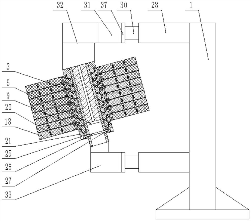
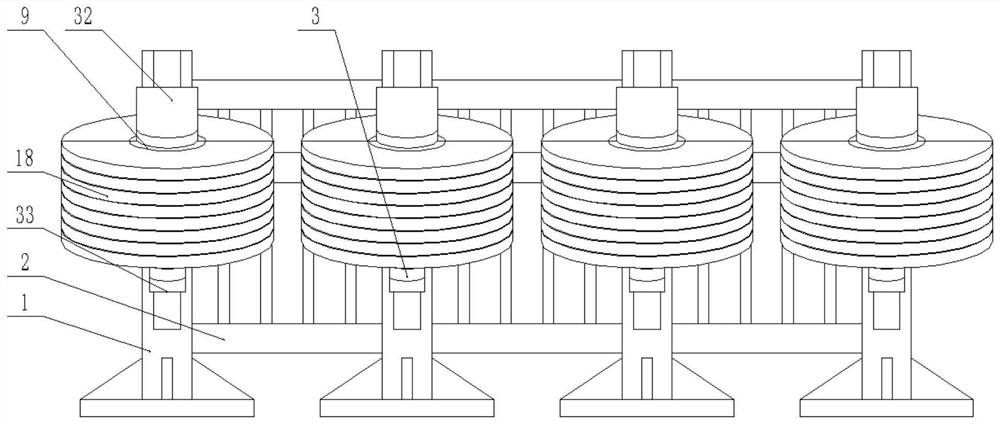
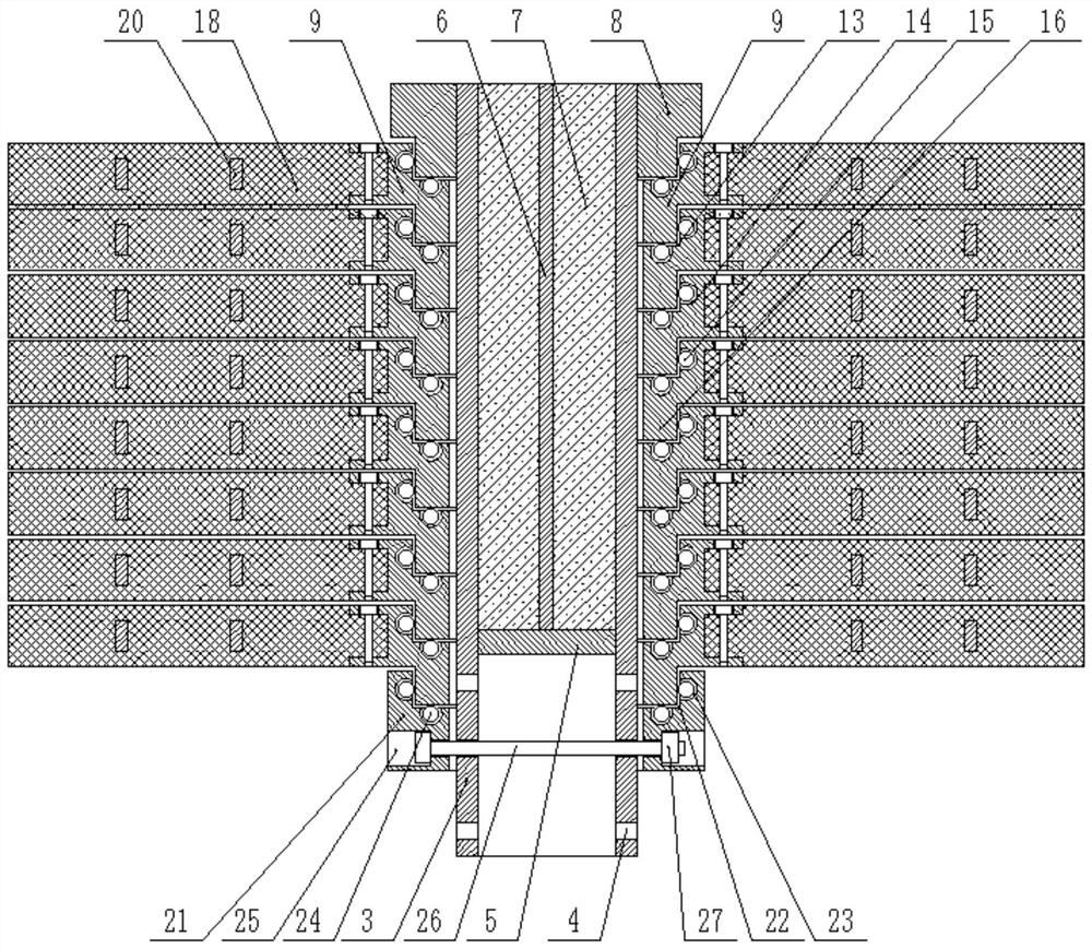
[0032] The present invention is specifically described below in conjunction with accompanying drawing, as Figure 1-9 shown.

[0033] The creative point of this scheme lies in the structural design of the assembled rotating anti-collision buffer device, combined with the attached figure 1 , attached figure 2 , attached image 3 , attached Figure 4 , attached Figure 5 , attached Image 6 , attached Figure 7, the assembled rotary anti-collision buffer device includes a fixed sleeve 3, and the lower end of the outer surface of the fixed sleeve 3 is provided with several groups of fixed through holes 4, and several groups of fixed through holes 4 are evenly distributed on the fixed sleeve 3, and each group of fixed through holes 4 is divided into two, the two fixed through holes 4 of the same group are located on both sides of the fixed sleeve 3, a sealing baffle 5 is installed below the inner center of the fixed sleeve 3, and a cross support frame 6 is installed on the ...


PUM


Abstract

The invention discloses an anti-collision buffer guardrail structure for bridge engineering. The structure comprises a plurality of fixed upright posts and guardrails mounted between two adjacent fixed upright posts, reinforcing support devices are arranged in the fixed upright posts, elastic collision buffer devices are arranged on the fixed upright posts, and an assembled rotary anti-collision buffer device is arranged on the elastic collision buffer device. Through rotation of the anti-collision buffering rotating disc and the elasticity of the anti-collision buffering rotating disc, the collision kinetic energy of automobile collision is effectively reduced, through inclined installation of the fixing sleeve, downward extrusion force is applied to an automobile, the situation that the automobile turns over is avoided, and through the use of a semicircular rotating anti-collision seat and a semicircular supporting rotating seat, the anti-collision buffering rotary disc can be rapidly installed and replaced, and a worker can conveniently maintain the guardrail, and the collision kinetic energy borne by the fixed stand column is effectively reduced through contact fit between the elasticity of a strong compression spring and a limiting sleeve and a buffering sleeve.

Description

technical field [0001] The invention relates to the field of equipment related to bridge protection, in particular to an anti-collision buffer guardrail structure for bridge engineering. Background technique [0002] With the rapid development of economy, automobiles are widely used as a convenient means of transportation. On ordinary roads or highways, traffic accidents occur frequently due to the excessive speed of vehicles, the most serious of which is that high-speed vehicles hit the guardrails on the side of the road, in the middle of the road or on the side of the bridge, and these guardrails are made of concrete. Bricks are either composed of concrete blocks arranged at intervals and cross rails connecting adjacent blocks, or steel structure cross bars and columns connected. However, these guard rails cannot absorb the impact kinetic energy of the car and are protected after collision. The reverse force of the hurdle, the car flips or reverses and deviates from the o...

Claims


Application Information

Patent Timeline
Patent Type & Authority Applications(China)
IPC IPC(8): E01D19/10
CPCE01D19/103Y02A30/30
Inventor 傅海龙杨同伟秦华李高杰董红锋毛晖曹艳艳茹宁史伟亚仝晓英程钢宋莉张志磊刘杨李方兵朱英豪朱亚兴郭凯
Owner 中铁十四局集团青岛工程建设有限公司
Why Eureka
Try Eureka