Outdoor water supply and drainage conveying channel

A water supply and drainage, open-air technology, applied in the direction of waterway system, sewer pipe system, cleaning sewer pipes, etc., can solve the problem of the accumulation of internal settled particles in one place for easy cleaning and reduction, so as to reduce the possibility of evaporation, reduce waste, The effect of reducing the amount of carry

Pending Publication Date: 2021-06-11
何兴树
View PDF0 Cites 0 Cited by
  • Summary
  • Abstract
  • Description
  • Claims
  • Application Information

AI Technical Summary

Problems solved by technology

[0005] Aiming at the deficiencies of the prior art, the present invention provides an open-air water supply and drainage channel, which solves the problem that the existing open-air water supply and drainage channel cannot accumulate the internally settled particles in one place for easy cleaning, and reduces the time spent cleaning the internal particles. The water brought out reduces the possibility of water being evaporated and reduces the waste of water resources

Method used


Image

  • Outdoor water supply and drainage conveying channel
  • Outdoor water supply and drainage conveying channel
  • Outdoor water supply and drainage conveying channel

Examples


Embodiment 1

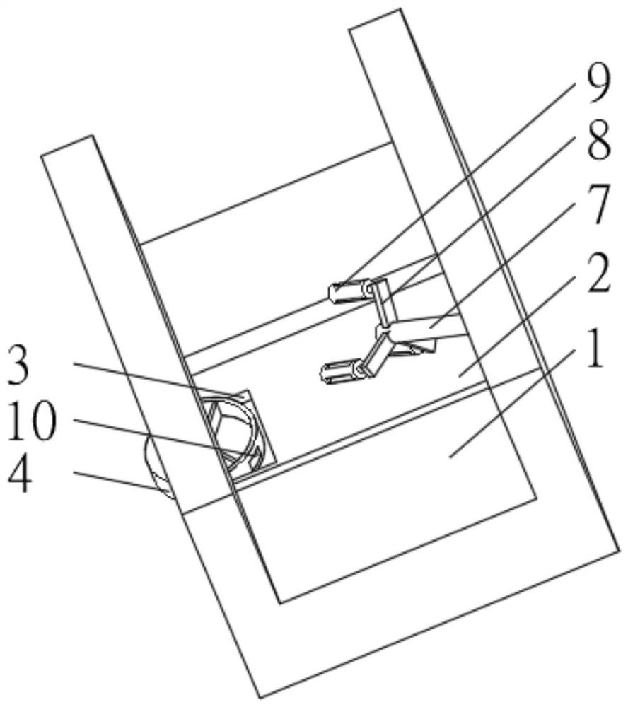
[0030] see Figure 1-2 , the present invention provides a technical solution: an open-air water supply and drainage channel, including a water delivery channel 1, a settling tank 2 is provided at the inner bottom of the water delivery channel 1, a collection tank 3 is opened at the inner bottom of the settlement tank 2, and the water delivery channel 1 The side of the inner wall away from the collection tank 3 is fixedly connected with a tilting rod 7, one end of the tilting rod 7 is rotatably connected with a swivel frame 8, and the end of the swivel frame 8 away from the tilting rod 7 is evenly equipped with a drainage device 9.

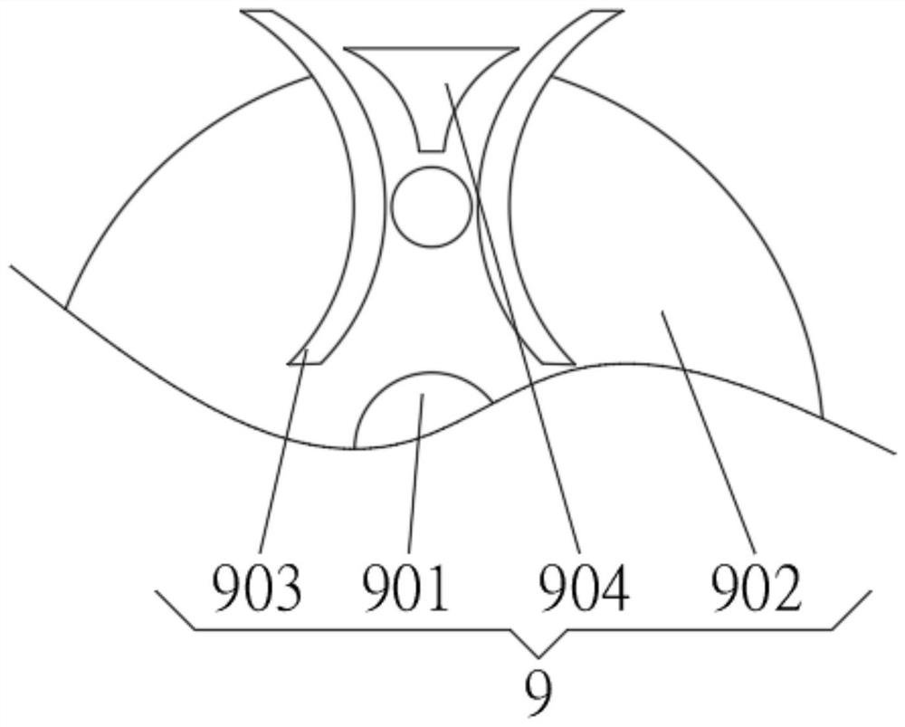
[0031] The drainage device 9 includes a drainage column 901, the outside of the drainage column 901 is provided with a drainage groove 902, and the inner wall of the drainage groove 902 is uniformly equipped with a vibrating plate 903, and the vibration plates 903 are connected in rotation, and the inner wall of the drainage groove 902 is close to t...

Embodiment 2

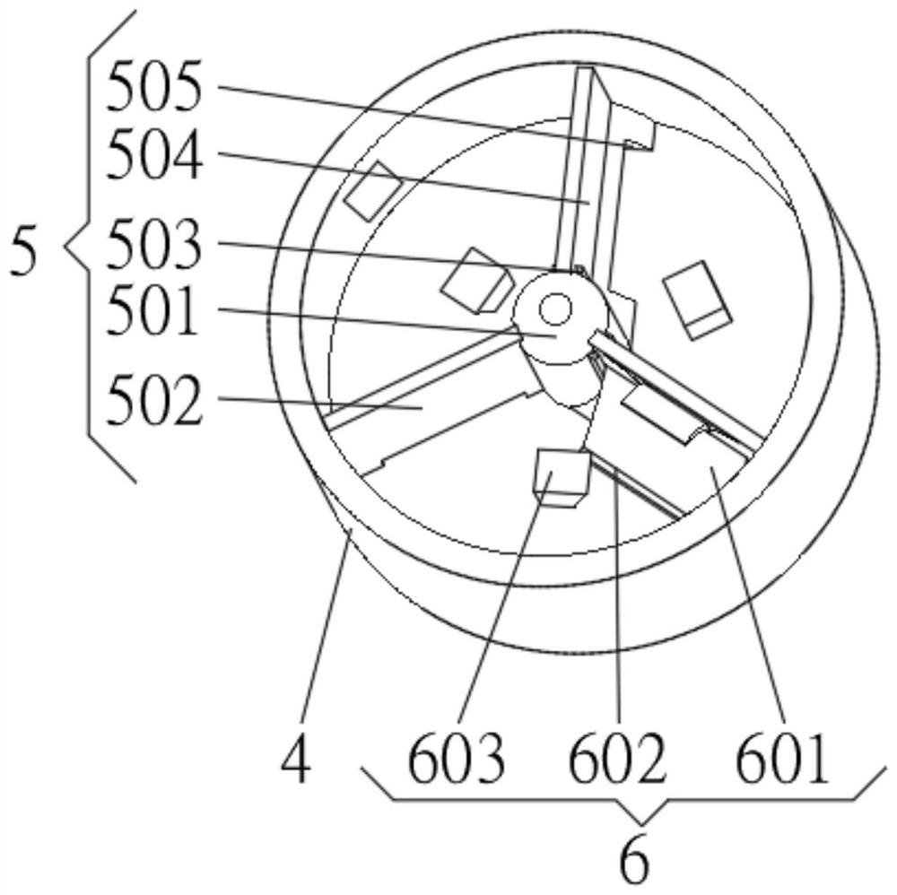
[0034] see Figure 1-6 , the present invention provides a technical solution: on the basis of Embodiment 1, a collection box 4 is installed on the inner bottom of the collection tank 3, the collection box 4 runs through the water supply channel 1 and extends to the outside of the water supply channel 1, and the collection box 4 is located at the water supply channel 1 One end inside the water canal 1 is designed as an opening, and the collection box 4 is provided with a collection hole 10 on one side inside the water supply canal 1 , and a collection device 5 is installed inside the collection box 4 .

[0035] The collection device 5 includes a central column 501, the outer side of the central column 501 is fixedly connected with a collecting plate 502, the outer side of the central column 501 is connected with a rotating plate 504 through a mounting frame 503, and the bottom of the rotating plate 504 is provided with a collecting hole 505.

[0036] The installation frame 503 in...

Embodiment 3

[0040] see Figure 1-6 , the present invention provides a technical solution: on the basis of Embodiment 2, a scraping device 6 is installed on one side of the collecting device 5, and the scraping device 6 is slidingly connected with the inner bottom of the collection box 4, and the scraping device 6 includes elastic Plate 601, the elastic plate 601 is connected with the rotating plate 504, the end of the elastic plate 601 away from the rotating plate 504 is fixedly connected with a scraping head 602, the inner bottom of the collection box 4 is evenly installed with a limit block 603, and one side of the limit block 603 is opened There is a limit groove compatible with the scraping head 602.

[0041] When in use, the elastic plate 601 is driven by the water flow to rotate simultaneously with the rotating plate 504, and the scraping head 602 is blocked by the limiting block 603 and then deformed and bent until the rotating plate 504 rotates to the limiting block 603 to push th...


PUM


Abstract

The invention discloses an outdoor water supply and drainage conveying channel, and relates to the technical field of water supply and drainage. The outdoor water supply and drainage conveying channel comprises a water supply channel, wherein a settling tank is formed in the bottom of the inner side of the water supply channel; a collecting tank is formed in the bottom of the inner side of the settling tank; a collecting box is installed at the bottom of the inner side of the collecting tank; the collecting box penetrates through the water supply channel and extends to the outside of the water supply channel; the end, located inside the water supply channel, of the collecting box is designed to be open; a collecting hole is formed in the side, located inside the water supply channel, of the collecting box; a collecting device is installed inside the collecting box; a scraping device is installed on one side of the collecting device; and the scraping device is in sliding connection with the bottom of the inner side of the collecting box. According to the outdoor water supply and drainage conveying channel, the purpose that internally settled particulate matter is accumulated in one place to be conveniently cleaned is achieved, water brought out when the internal particulate matter is cleaned is reduced, the possibility that the water is evaporated is reduced, and waste of water resources is reduced.

Description

technical field [0001] The invention relates to the technical field of water supply and drainage, in particular to an open-air water supply and drainage delivery channel. Background technique [0002] Water supply and drainage design is an important part of architectural design, which has a huge impact on the daily life of residents, and its role cannot be ignored. Water supply and drainage generally refers to urban water supply systems, drainage systems (municipal water supply and drainage and building water supply and drainage ), referred to as water supply and drainage. [0003] Water supply and drainage are usually transported by pipelines, and open-air channels are also used for long-distance transport. However, the existing open-air transport channels for water supply and drainage cannot accumulate internal settled particles in one place for easy cleaning. When cleaning internal particles It is easy to bring out more water, which increases the possibility of water bei...

Claims


Application Information

Patent Timeline
Patent Type & Authority Applications(China)
IPC IPC(8): E03F3/04E03F7/00E03F9/00
CPCE03F3/046E03F7/00E03F9/002
Inventor 何兴树
Owner 何兴树
Why Eureka
Try Eureka