
Digital electronic detonator detonation management and control system for perforation and method

A digital electronic detonator and electronic detonator technology, applied in earthwork drilling, mining fluid, borehole/well components, etc., can solve problems such as well jamming, perforating gun bursting, and mining project progress lagging behind, achieving a simple method and improving safety effect

Active Publication Date: 2021-06-11
CHUANNAN ENERGY TECH CO LTD
View PDF8 Cites 1 Cited by
  • Summary
  • Abstract
  • Description
  • Claims
  • Application Information

AI Technical Summary

Problems solved by technology

However, the above-mentioned technologies cannot automatically identify digital IDs, have no detonation codes or are not connected to the National Industrial Electronic Detonator Center
The patent application document CN201810553208.4 provides an electronic detonator for oil and gas wells, which realizes precise control of the downhole electronic detonator by sending codes through ground control. Due to the uniqueness of the downhole electronic detonator control code, this technology cannot achieve multi-level control and is not applicable in unconventional oil and gas development
At the same time, due to the huge energy generated by the explosion of shaped energy perforating charges, it is easy to cause conventional perforating guns to burst or excessive plastic deformation, resulting in accidents such as well jamming, which seriously delays the progress of mining projects and causes large financial losses
[0004] Based on the above, it is hoped to propose a more reliable perforating gun detonation control system to solve the inconvenience caused by the above problems

Method used


Image

  • Digital electronic detonator detonation management and control system for perforation and method
  • Digital electronic detonator detonation management and control system for perforation and method
  • Digital electronic detonator detonation management and control system for perforation and method

Examples


Embodiment Construction

[0039] In order to make the purpose, technical solutions and advantages of the embodiments of the present invention clearer, the technical solutions in the embodiments of the present invention will be clearly and completely described below in conjunction with the drawings in the embodiments of the present invention. Obviously, the described embodiments It is a part of embodiments of the present invention, but not all embodiments. The components of the embodiments of the invention generally described and illustrated in the figures herein may be arranged and designed in a variety of different configurations.

[0040] Accordingly, the following detailed description of the embodiments of the invention provided in the accompanying drawings is not intended to limit the scope of the claimed invention, but merely represents selected embodiments of the invention. Based on the embodiments of the present invention, all other embodiments obtained by persons of ordinary skill in the art wi...


PUM


Abstract

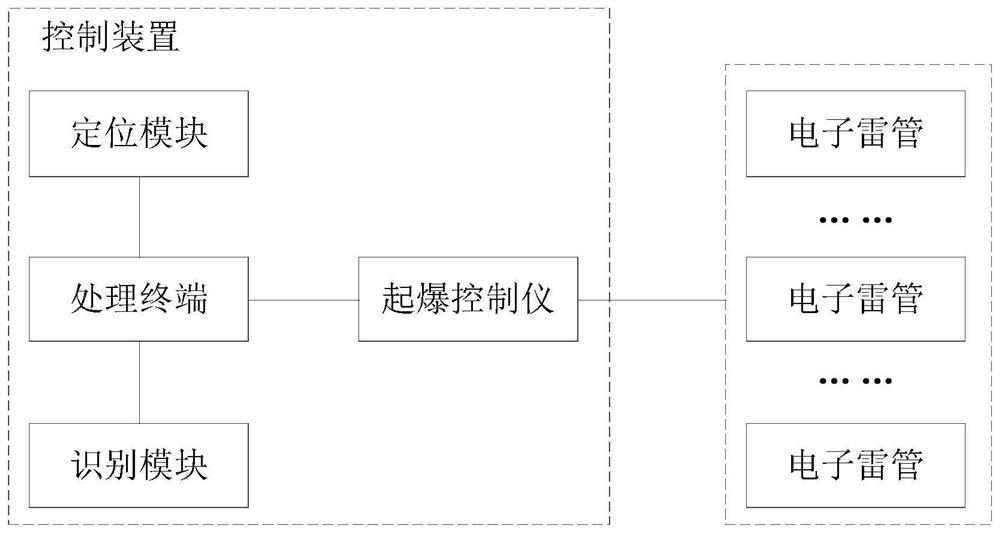
The invention provides a digital electronic detonator detonation management and control system for perforation and a method for the system. The system comprises a control device and a perforation device, the perforation device comprises a perforation gun, a plurality of electronic detonators and a plurality of perforation bullets, and each electronic detonator comprises an explosion part and a coding control part; and the control device is used for setting and checking detonation data and outputting detonation information to each coding control part, and each coding control part is used for checking the detonation information and controlling each explosion part to detonate. The system is strict in detonation management and control and has higher detonation safety; the clock information of each electronic detonator and the clock information of a processing terminal are consistent through multi-clock calibration, clock drifting caused by the environment is avoided, and it is guaranteed that detonation operation is completed in a high-quality mode; and in addition, the system also adopts the perforation gun with a reinforced structure, so that the perforation gun can be effectively prevented from bursting and excessive plastic deformation during use, the well jamming accident is avoided, and the perforation operation is effectively ensured to be carried out.

Description

technical field [0001] The invention relates to the technical field of perforation blasting, in particular to a digital electronic detonator detonation control system and method for perforation. Background technique [0002] Unconventional oil and gas reservoirs such as shale gas and tight oil and gas are adsorbed or dissociated in organic-rich mudstone interlayers, and are very rich in reserves in my country. In its development, the combination of cable multi-stage cluster perforation and bridge plug is currently the most widely used development method at home and abroad. The pipe string is transported through the cable, and multiple electric detonators and bridge plugs are sequentially ignited, set and multi-stage The hierarchical control perforation penetrates the casing and the formation, providing a prerequisite for staged fracturing. [0003] The patent application document CN201821444203.X and the patent application document CN201410513842.7 respectively provide an o...

Claims


Application Information

Patent Timeline
Patent Type & Authority Applications(China)
IPC IPC(8): E21B43/1185
CPCE21B43/1185E21B43/11857
Inventor 徐德昭重成兴陈宇郑伦贵张成彬殷腾黄河付团辉朱舰桥陈惠卿
Owner CHUANNAN ENERGY TECH CO LTD
Learn More