A centralized exhaust device for a refrigeration machine room

A technology of exhaust device and refrigeration machine room, which is applied in the direction of mechanical equipment, pipe components, pipes/pipe joints/pipe fittings, etc., and can solve the problems of affecting the environment of the machine room, spraying water mist, and heavy workload.

Active Publication Date: 2021-10-26
中建五局安装工程有限公司
View PDF14 Cites 0 Cited by
  • Summary
  • Abstract
  • Description
  • Claims
  • Application Information

AI Technical Summary

Problems solved by technology

[0003] However, there will be the following disadvantages in the actual use process: 1. During the initial pressure test and later maintenance of the refrigeration room, it is necessary to repeatedly use ladders to climb to the top of the pipeline. The workload is heavy and the cost is high. Stamping on the top of the pipeline will damage the insulation of the pipeline; 2. , The automatic exhaust valve is set on the top of the pipeline in the computer room, and water mist will be sprayed out with the gas when exhausting, which will affect the environment of the computer room

Method used


Image

  • A centralized exhaust device for a refrigeration machine room
  • A centralized exhaust device for a refrigeration machine room

Examples


Embodiment Construction

[0018] The following will clearly and completely describe the technical solutions in the embodiments of the present invention with reference to the accompanying drawings in the embodiments of the present invention. Obviously, the described embodiments are only some, not all, embodiments of the present invention. Based on the embodiments of the present invention, all other embodiments obtained by persons of ordinary skill in the art without making creative efforts belong to the protection scope of the present invention.

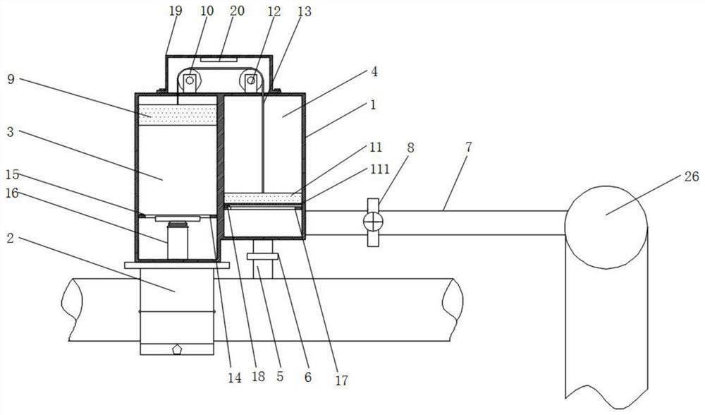
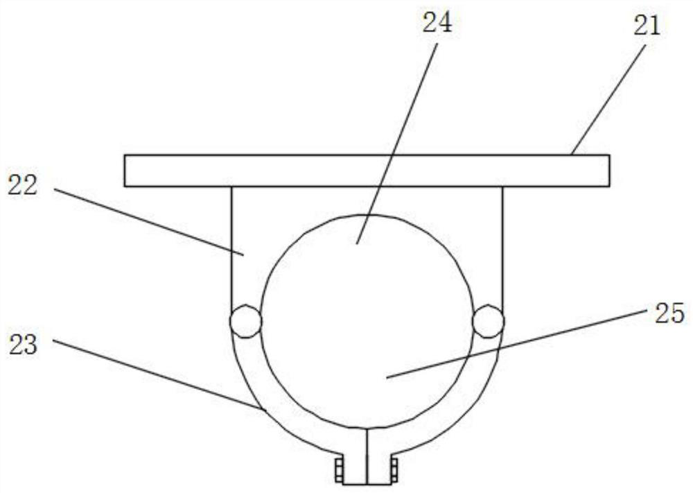
[0019] see Figure 1-2 , an embodiment provided by the present invention: a centralized exhaust device for a refrigeration machine room, the exhaust device is arranged on the top of the highest point of each refrigeration pipe in the refrigerator room, the exhaust device includes a main unit, a constant negative pressure generating unit and an electric control unit Reset unit; the main unit includes an outer shell 1, a clamping part 2 arranged at the bottom of...


PUM


Abstract

The invention discloses a centralized exhaust device for a refrigerating machine room. The exhaust device is arranged on the top of the highest part of each refrigeration pipe in the refrigerating machine room. The exhaust device includes a main body unit, a constant negative pressure generating unit and an electric control reset unit . In the present invention, because the weight of the counterweight one is greater than the weight of the counterweight two, the counterweight one will generate an upward pulling force on the counterweight two through the connecting rope, and the pulling force remains constant. The freezing pipe is connected, the freezing pipe has frozen water, and the inside of the air collecting chamber under the piston is relatively sealed, so a constant "negative pressure" state will be generated inside the air collecting chamber under the piston, so that once there is gas in the freezing pipe, It will speed up the gas inside the freezing pipeline entering the gas-collecting cavity, and when the gas in the freezing pipeline enters, the second counterweight will drive the piston to move upward, and the first counterweight will move downward, so that the inside of the gas-collecting cavity will always maintain a negative pressure state .

Description

technical field [0001] The invention relates to the technical field of exhaust devices, in particular to a centralized exhaust device for a refrigeration machine room. Background technique [0002] The chilled water pipeline at the highest point of the original refrigeration room needs to be equipped with an automatic exhaust valve to eliminate the gas collection in the pipeline, so as to facilitate the smooth flow of water in the pipeline and avoid air blockage, so as to realize the corresponding functions. [0003] However, there will be the following disadvantages in the actual use process: 1. During the initial pressure test and later maintenance of the refrigeration room, it is necessary to repeatedly use ladders to climb to the top of the pipeline. The workload is heavy and the cost is high. Stamping on the top of the pipeline will damage the insulation of the pipeline; 2. , The automatic exhaust valve is set on the top of the pipeline in the equipment room. When exhau...

Claims


Application Information

Patent Timeline
Patent Type & Authority Patents(China)
IPC IPC(8): F16L55/07
CPCF16L55/07
Inventor 刘鑫铭曾超林屈波姚传联唐二隆
Owner 中建五局安装工程有限公司
Why Eureka
Try Eureka