A film coating device for a packaging machine

A film device and packaging machine technology, applied in the direction of packaging material feeding device, packaging, transportation packaging, etc., can solve problems such as tearing, increased material costs, and packaging film not fully tensioned

Active Publication Date: 2021-07-06
无锡喝彩包装制品有限公司
View PDF6 Cites 0 Cited by
  • Summary
  • Abstract
  • Description
  • Claims
  • Application Information

AI Technical Summary

Problems solved by technology

[0005] It is worth noting that, whether it is the traditional technology of the film device or the above-mentioned authorization documents, the rotation speed of a pair of front-feeding film pressing rollers is greater than that of a pair of rear-feeding film pressing rollers. The disadvantage of this solution lies in the actual operation of the staff. It is difficult to control the speed difference between the two pairs of film feeding rollers. If the speed difference is large, the packaging film will be easily deformed and severely vertically torn. If the speed difference is small, the packaging film will not be fully tensioned, especially for different When packaging a bottle with a large size, the movement of the cutter will cause the length of the cut film to change, that is, the speed difference between the two pairs of film feeding rollers needs to be adjusted again to continue to accurately control the tension of the packaging film. Part of the speed difference is more difficult to control, so it takes a lot of time and materials to conduct trial and error experiments every time you switch the size of the packaging bottle, which not only increases the material cost, but also greatly delays the production capacity of the production line. The bottle can be quickly adjusted on the membrane device is particularly important

Method used


Image

  • A film coating device for a packaging machine
  • A film coating device for a packaging machine
  • A film coating device for a packaging machine

Examples


Embodiment

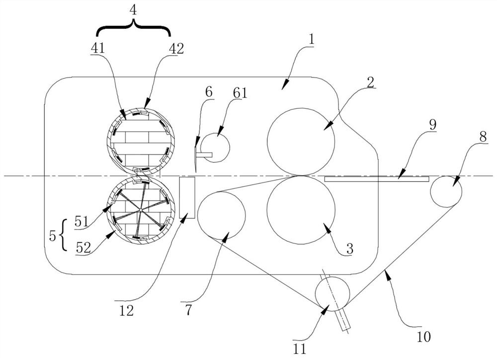
[0028] refer to Figure 1-4 , a film coating device for a packaging machine, comprising: a pair of front film feed rollers and a pair of rear film feed rollers arranged on a base plate 1, and a pair of front film feed rollers include front film top pressure rollers that are cooperating up and down. 2 and the front film feeding lower pressure roller 3, a pair of rear film feeding pressure rollers include the rear film feeding upper pressure roller 4 and the rear film feeding lower pressure roller 5, which are arranged up and down, between the front and rear two pairs of film feeding pressure rollers A cutter shaft 61 equipped with a cutter 6 is provided, the cutter 6 is positioned above the packaging film, a backing plate 12 for cutting with the cutter 6 is provided below the packaging film, and a front auxiliary feeder is provided below the cutter 6. The film roller 7 is provided with a rear auxiliary film delivery roller 8 on the outside of the front film lower pressure rolle...


PUM


Abstract

The invention discloses a film feeding device for a packaging machine, which comprises a pair of front film feeding pressure rollers and a pair of rear film feeding pressure rollers arranged on a base plate. Roller and front film feeding lower pressure roller, forward film feeding upper pressing roller, forward film feeding lower pressing roller, rear film feeding upper pressing roller, rear film feeding lower pressing roller are coaxially fixedly connected with front upper gear, front lower gear, Rear upper gear, rear lower gear, the four gears are located on the end face of the base plate away from the four pressure rollers, the front upper gear and the front lower gear are matched, and the rear upper gear and the rear lower gear are matched. The advantage is that the front film feeding pressure roller drives the friction cone to rotate through the pulley, and the truncated structure of the friction cone makes it change when different positions of the friction cone contact the friction disc, so that the speed of the rear film feeding pressure roller in this device It is in a controllable state, avoiding the problem of a single application range caused by the constant speed difference between the front film feeding pressure roller and the rear film feeding pressure roller.

Description

technical field [0001] The invention relates to the technical field of packaging machinery, in particular to a film coating device for a packaging machine. Background technique [0002] The structure of the film loading device in the traditional packaging machine includes: a pair of forward film pressure rollers and a pair of rear film pressure rollers that rotate under the drive of the driving mechanism. The speed of the front film pressure rollers is greater than that of the rear film pressure rollers The speed of the rotating speed, the rear film head of the packaging film after cutting by the cutter can fall on the supporting film plate. When working, the cutting knife cuts the packaging film and the front film is transported to the The bottle conveying plane is used for bottle packaging, and the film head of the rear section of the film falls on the supporting film plate under the cutter, and is pushed forward along the supporting film plate by the rear film feeding pre...

Claims


Application Information

Patent Timeline
Patent Type & Authority Patents(China)
IPC IPC(8): B65B41/16B65H23/26
CPCB65B41/16B65H23/26
Inventor 侯世杰黄奥煜
Owner 无锡喝彩包装制品有限公司
Why Eureka
Try Eureka