Adhesive tape pasting mechanism and adhesive tape pasting device

A glue sticking mechanism and tape technology are applied in transportation and packaging, assembling battery machines, electrochemical generators, etc., which can solve the problems of many technological processes and large equipment occupation of the sticking device, so as to save tape preparation and handling. Tape, easy to cut, to speed up the effect of glue sticking efficiency

Pending Publication Date: 2021-06-11
WUXI LEAD INTELLIGENT EQUIP CO LTD
View PDF0 Cites 3 Cited by
  • Summary
  • Abstract
  • Description
  • Claims
  • Application Information

AI Technical Summary

Problems solved by technology

[0004] This application provides a gluing mechanism and a gluing device to solve the technical defects of the prior art that the gluing device has many process flows and the equipment occupies a large area

Method used


Image

  • Adhesive tape pasting mechanism and adhesive tape pasting device
  • Adhesive tape pasting mechanism and adhesive tape pasting device
  • Adhesive tape pasting mechanism and adhesive tape pasting device

Examples


other Embodiment approach

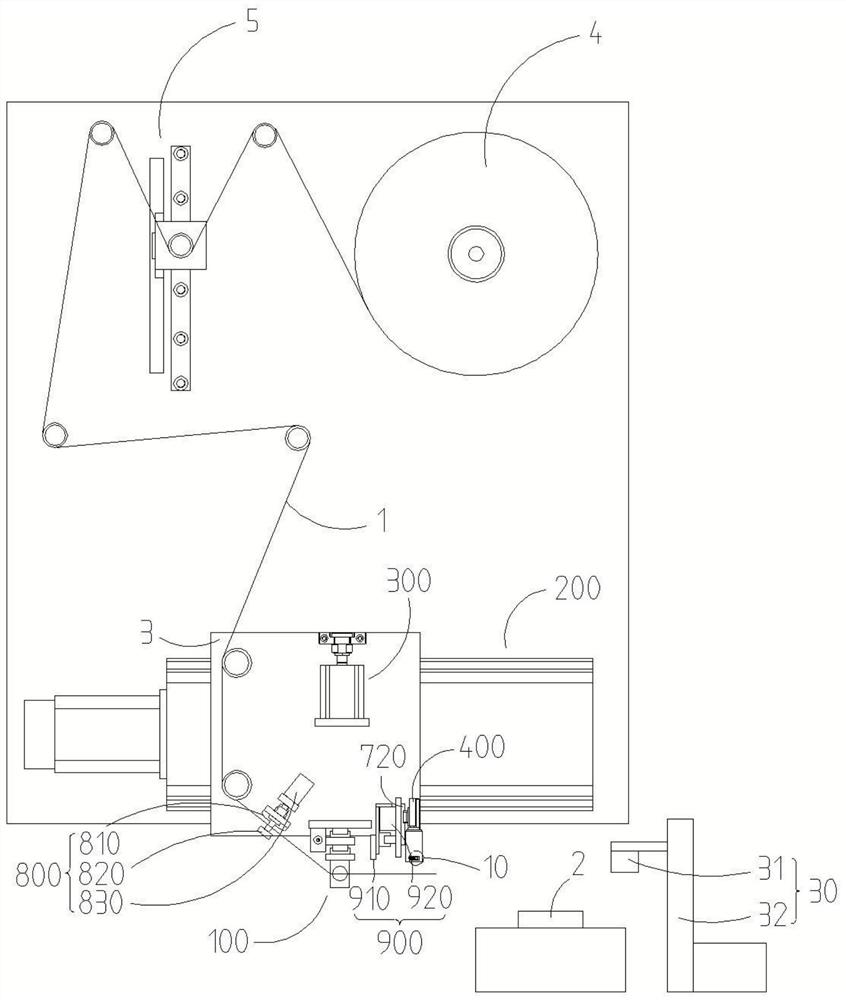
[0033] In other embodiments, according to the configuration or arrangement of the parts to be glued 2, the paths of the first drive assembly 200 and the second drive assembly 300 may also be inclined or curved, as long as the drive pull assembly 100 can be driven to pull the adhesive tape 1 to the position to be glued, stick the tape 1 to the part 2 to be glued, and the first pressure roller 10 smoothes the tape 1 and realizes the bending and pasting of the tape 1.

[0034] It should be explained that the above-mentioned "position to be glued" refers to the first surface of the piece to be glued 2, the initial position to be glued, and the end of the adhesive tape 1 held by the glue pulling assembly 100 is attached to this position. According to the needs of the process, this position may be on the edge of the piece to be glued 2, and may also be in the middle of the piece to be glued 2. Because the glue pulling assembly 100 pulls the end of the adhesive tape 1, when the end o...

other Embodiment approach

[0059] In other embodiments, the first pressure roller buffer 720 can also use elastic members such as springs; at this time, by setting the first pressure roller buffer 720 between the first pressure roller 10 and the first pressure roller drive assembly 400; Alternatively, when the first pressing roller 10 and the first pressing roller driving assembly 400 are connected together, the first pressing roller buffer 720 is arranged between the first pressing roller driving assembly 400 and the frame on which the first pressing roller driving assembly 400 is installed. Between; through the elastic deformation of the elastic member, offset the excess travel of the first pressing roller driving assembly 400 .

[0060] Further, the first pressing roller 10 is arranged on the first pressing roller seat 30, the first pressing roller seat 30 is provided with a mounting hole 31, the end of the first pressing roller 10 is arranged in the mounting hole 31, and the first pressing roller An...


PUM


Abstract

The invention discloses an adhesive tape pasting mechanism and an adhesive tape pasting device. The adhesive tape pasting mechanism comprises an adhesive tape pulling assembly, a first compression roller, anadhesive tape cutting assembly, a first driving assembly and a second driving assembly. After the adhesive tape pulling assembly pulls the adhesive tape, the first driving assembly and the second driving assembly can drive the adhesive tape pulling assembly and the adhesive tape to move towards the to-be-pasted piece until the adhesive tape is pasted to the to-be-pasted piece; the first compression roller driving assembly can drive the first compression roller to compress the adhesive tape on the to-be-pasted piece; after the adhesive tape pulling assembly loosens the adhesive tape, the first driving assembly can reversely drive the adhesive tape pulling assembly to return, and the first compression roller can flatten the adhesive tape along with the adhesive tape pulling assembly; when the first compression roller reaches the edge of the to-be-pasted piece, the first compression roller driving assembly can drive the first compression roller to paste the adhesive tape to the second face of the to-be-pasted piece along the edge of the to-be-pasted piece; by means of the first compression roller driving assembly and the first compression roller, the adhesive tape can be bent along the to-be-pasted part while the adhesive tape is flattened and tightly attached, and the pasting requirements of the two faces of the to-be-pasted piece are met; and the pasting efficiency is high.

Description

technical field [0001] The present application relates to the technical field of battery manufacturing equipment, in particular to a gluing mechanism and a gluing device. Background technique [0002] The surface of the battery or battery cell needs to be glued. Under some special requirements, the tape needs to be pasted on one side of the battery first, bent, and then pasted on the other side of the battery. [0003] In the traditional gluing device, the adhesive tape is usually prepared first, then transported to the battery, and then pasted; this type of equipment has many technological processes and occupies a large area. Furthermore, in order to make the adhesive tape have a bent portion corresponding to the shape of the battery, traditional equipment also needs to be equipped with an adhesive tape deformation mechanism, which increases the cost. Contents of the invention [0004] The application provides a gluing mechanism and a gluing device to solve the technical...

Claims


Application Information

Patent Timeline
Patent Type & Authority Applications(China)
IPC IPC(8): H01M10/04H01M6/00B65H35/06
CPCB65H35/06H01M6/005H01M10/0404Y02P70/50
Inventor 不公告发明人
Owner WUXI LEAD INTELLIGENT EQUIP CO LTD
Why Eureka
Try Eureka