Automatic Peripheral Cleaning Mopping Vehicle

A mopping and automatic technology, applied in the direction of cleaning carpets, cleaning floors, automatically detecting obstacles, etc., to achieve the effect of expanding the scope of use, reducing the length of the car body, and reducing the space of the car body

Active Publication Date: 2022-04-26
SUINING CHANGFENG MECHANICAL TECH
View PDF9 Cites 0 Cited by
  • Summary
  • Abstract
  • Description
  • Claims
  • Application Information

AI Technical Summary

Problems solved by technology

[0003] The purpose of the present invention is to overcome the shortcomings of the existing reel-type floor mopping vehicles, and proposes a technical solution in which there are no chutes on both sides of the runner, and the substrate is directly surrounded by the runner from the outside of the runner, that is, automatic peripheral cleaning. Mopping vehicle, hereinafter referred to as mopping vehicle

Method used


Image

  • Automatic Peripheral Cleaning Mopping Vehicle
  • Automatic Peripheral Cleaning Mopping Vehicle
  • Automatic Peripheral Cleaning Mopping Vehicle

Examples


Embodiment Construction

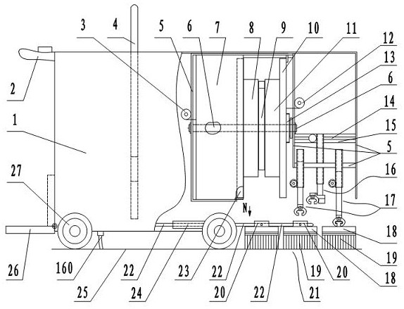
[0025] figure 1 In the figure is the overall structure diagram of the mopping vehicle. The floor mopping vehicle comprises a variable cleaning tank 7, a shell frame device, a pivoting arm device, a runner, a guide clip device, a car body, and a mopping handkerchief. Above the front wheel 27 in the car body is a variable cleaning pool 7. The variable cleaning pool 7 is referred to as the cleaning pool 7 hereinafter. The cleaning tank 7 is in the shape of a cylindrical shell, and the circular shell faces left and right. The cleaning pool right side among the figure is runner, and runner is made up of left runner 8 and right runner 11. The middle of the left and right runners are connected as one. A main shaft 6 passes through the center of the cleaning tank and the center of the runner. Main shaft 6 two ends are fixed on the frame 5 on the left side and the right side of the cleaning tank. The axle sleeve left side of left runner 8 is movably connected with left housing co...


PUM


Abstract

The automatic peripheral cleaning mop and mopping car includes a variable cleaning pool, a frame device, a turning clip device, a side clip device, a turning arm device, a runner, a guide clip device, a car body, and a mop. The mop strips are attached to a thin plastic substrate. The rear end of the roll arm is connected with a roll left shaft and a roll right shaft. When mopping and transferring the mop, connect the frame on the mop. When cleaning the mop, the rotary clamp device transfers the mop in the first row in front of the car to the bottom of the runner, and hangs the two ends of the mop substrate by the hanging clip of the rotary arm device, and wraps the substrate around the runner removed from the cleaning pool. On the outer circle and automatically fix both ends of the substrate. The guide clip device clamps the rear third and second rows of mopping pads and pushes forward in turn to make up. The cleaned mop is transferred to the mop space in the third row for mopping. The cleaned mop can be quickly removed from the mopping vehicle to manually mop the floor in many obstacles and narrow areas. Three rows of mopping pads take turns to clean and mop the floor, the floor is cleaner, the work efficiency is higher, and the use is more convenient. There are hand-push, ride-on and driverless models.

Description

technical field [0001] The invention belongs to the field of environmental protection machinery, in particular to an automatic peripheral cleaning mopping handkerchief and floor mopping vehicle. Background technique [0002] It is very common for strip-shaped dragging handkerchiefs to be used in office areas, communities, schools, hospitals, and families. But the cleaning and dehydration of the strip mopped handkerchief are very inconvenient. Mopping machines with automatic cleaning and dehydration, such as: reel type automatic cleaning and mopping machine, patent number: ZL201810710326.1; reel cleaning type continuous mopping machine, patent number: ZL 201821033792.2, etc. The base sheet connected with the handkerchief strips under the handkerchief is inserted into the shell plate with chutes on both sides, a runner is arranged in the cleaning pool, and chutes are provided on both sides of the outer circle of the runner. When cleaning, align the chutes on both sides of th...

Claims


Application Information

Patent Timeline
Patent Type & Authority Patents(China)
IPC IPC(8): A47L11/293A47L11/40
CPCA47L11/293A47L11/4038A47L11/40A47L11/4072A47L11/4061A47L2201/00A47L2201/028A47L2201/04
Inventor 邹家福邹永平
Owner SUINING CHANGFENG MECHANICAL TECH
Why Eureka
Try Eureka