a 3d printer

A technology of 3D printer and printing device, applied in the direction of 3D object support structure, coating device, manufacturing tool, etc., can solve the problem of uncontrollable changes in viscous cooling speed of connection parts with different layers, slow cooling efficiency of fans, and material blanking. Inaccurate and other problems, to achieve high transmission accuracy and bearing capacity, reduce printing accuracy, and reduce the effect of impact

Active Publication Date: 2021-12-14
SHENZHEN ATOMSTACK TECH CO LTD
View PDF12 Cites 0 Cited by
  • Summary
  • Abstract
  • Description
  • Claims
  • Application Information

AI Technical Summary

Problems solved by technology

[0006] The purpose of the present invention is to provide a 3D printer, which solves the problem that the cooling efficiency of the fan is slow when the 3D printer is in use, the wind blowing will affect the printing direction, and the vibration of the fan installed on the side will make the material blanking inaccurate, and at the same time cannot Control the change of viscosity and cooling rate of connection parts with different layers

Method used


Image

  • a 3d printer
  • a 3d printer
  • a 3d printer

Examples


no. 1 example

[0037] The basic principles, main features and advantages of the present invention have been shown and described above. Those skilled in the art should understand that the present invention is not limited by the above-mentioned embodiments. What are described in the above-mentioned embodiments and the description are only the principles of the present invention. Variations and improvements, which fall within the scope of the claimed invention. The scope of protection required by the present invention is defined by the appended claims and their equivalents.

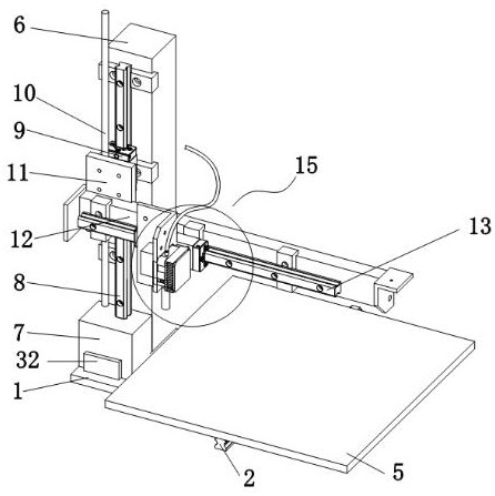
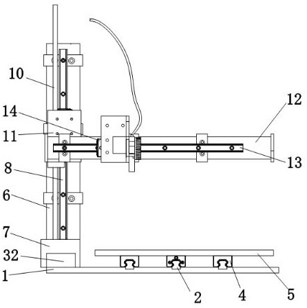
[0038] refer to Figure 1-9 , the present invention provides a 3D printer, including an underframe 1, a power unit and a printing device 15 are arranged on the top of the underframe 1.

[0039] The power device includes a plurality of first slide rails 2, the first slide rails 2 are evenly distributed in an array and are fixedly connected to the top of the chassis 1, and the inside of the first slide rail 2 is slidingly ...

no. 2 example

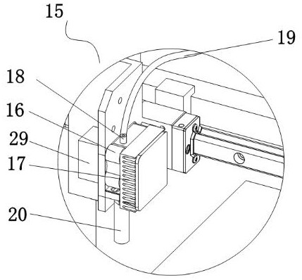
[0051] Based on the 3D printer provided in the first embodiment, the same layer printing can effectively realize rapid cooling in specific use, but when printing layer by layer, especially when printing, the thickness of the printed part increases continuously with the increase of the number of layers. When it is too large, if the bottom is too thin, the viscosity of the connection position is poor, and because the width of the molten material ejected from the nozzle 20 is constant, if the second layer wants to increase the thickness, it needs to be stacked in a staggered manner. It is very easy to tilt or collapse when it is in place. At the same time, if the wall thickness of one side is increased, if the width of the nozzle 20 does not change, it will not be able to process at all. To solve this problem, improve the stability of the connection position when 3D printing is printing layer by layer , combined with Figure 10-11 , the 3D printer also includes: electromagnetic v...


PUM


Abstract

The present invention relates to the technical field of printing equipment, in particular to a 3D printer, comprising an underframe, a power device and a printing device are provided on the top of the underframe, the printing device includes a booster, and a bottom of the booster is provided with A heater, the bottom of the heater is provided with a spray head, the top of the booster is connected with a feed port, the inside of the feed port is slidably connected with a material pipe, and the outer surface of the spray head is evenly arrayed with a plurality of A coolant tank, a fan-shaped fan is arranged between the adjacent coolant tanks. The device cooperates with fan fan, coolant tank, ring box, solenoid valve and heat-resistant elastic end to jointly solve the problems of high temperature, fan vibration, fixed-point cooling and increased printing wall thickness in the device. The material is cooled quickly and efficiently at a fixed point, and the opening shape and size of the heat-resistant elastic end can be changed according to the change of the wall thickness to adapt to the printing thickness, and the rapid cooling position and efficiency can be changed according to the printing thickness adaptation.

Description

technical field [0001] The invention relates to the technical field of printing equipment, in particular to a 3D printer. Background technique [0002] 3D Printers (3D Printers) for short (3DP) is a magical printer designed by an inventor named Enrico Dini, which can not only "print" a complete building, but even Print the shape of any desired item in the spaceship for the astronauts. But what 3D prints out is the model of the object, not the function of the object. [0003] Existing 3D printers mostly use fans to cool the printing process. This cooling method is slow in efficiency. At the same time, according to the change of the printing direction of the nozzle, the fan cannot change the cooling direction accordingly, so the vibration of the fan and the direction of its wind force will affect the printing process. process affects. [0004] At the same time, in the current 3D printing process, it is impossible to quickly and efficiently cool the molten printing material ...

Claims


Application Information

Patent Timeline
Patent Type & Authority Patents(China)
IPC IPC(8): B29C64/205B29C64/209B29C64/30B29C35/16B29C64/295B29C64/232B29C64/236B33Y30/00B33Y40/00
CPCB29C64/205B29C64/209B29C64/30B29C35/16B29C64/295B29C64/232B29C64/236B33Y30/00B33Y40/00B29C2035/1658
Inventor 白万涛
Owner SHENZHEN ATOMSTACK TECH CO LTD
Why Eureka
Try Eureka