
Eureka
For R&D, Eureka makes reading and utilizing patents & technical documents easy.
Eureka AIR
Designed for self-driven R&D workflows. Generate viable solutions, solve complex R&D challenges, empower your innovation with AI.

Eureka Materials
Designed for material experts only. Revolutionize your material R&D, from search, analyze, to developing new materials.

TechResearch
Generate reliable direction feasibility study reports for your R&D in just a few steps.

TechSeek
Discover and master advanced knowledge NOW. Basics, ideas, possibilities, all at once.

TechMind
As an expert in R&D Theories, TechMind can generates customized viable solutions instantly.

TechRisk
Analyze your overall solution with one click, know your potential R&D risks in advance.

TechMonitor
Get weekly tech updates, stay abreast of the latest tech innovations and key insights.
Intelligent combined stretching type teaching board
A teaching board and stretching technology, applied in the field of teaching boards, can solve the problems of large teaching boards, inconvenient use, occupying space, etc., and achieve the effects of saving space, being convenient to use, and preventing falling off.
- Summary
- Abstract
- Description
- Claims
- Application Information
AI Technical Summary
Problems solved by technology
Method used
Image

Examples
Embodiment 1
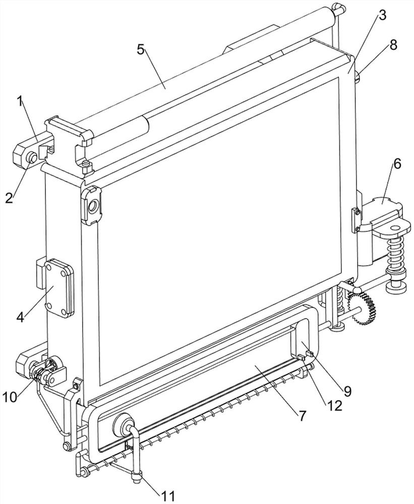
[0038] An intelligent combination stretching teaching board, such as figure 1 , figure 2 , image 3 and Figure 4 As shown, it includes a stabilizer 1, bolts 2, the first teaching board 3, a telescopic mechanism 5 and an access mechanism 6, the rear side of the first teaching board 3 is connected with a stabilizer 1, and the left and right sides of the stabilizer 1 are provided with two A bolt 2, a telescopic mechanism 5 is installed on the top of the first teaching board 3, and an access mechanism 6 is installed on the lower right side of the first teaching board 3.
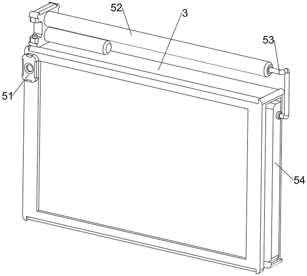
[0039] The telescoping mechanism 5 includes a photosensitive sensor 51, an electric push rod 52, a connecting rod 53 and a second teaching board 54. A photosensitive sensor 51 is installed on the upper left part of the front side of the first teaching board 3, and an electric push rod is installed on the top of the first teaching board 3. 52, the right end of the telescopic rod of the electric push rod 52 is...
Embodiment 2
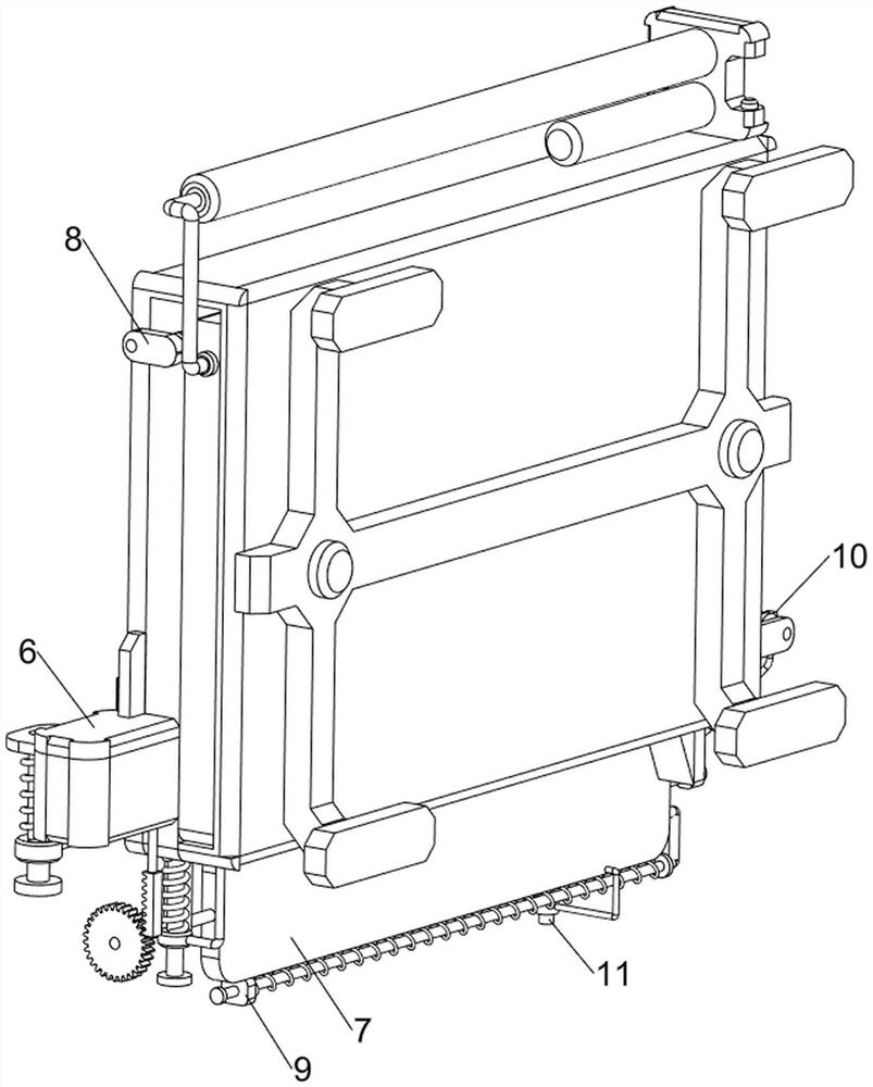
[0043] On the basis of Example 1, such as figure 1 , figure 2 , Figure 5 , Image 6 , Figure 7 , Figure 8 , Figure 9 , Figure 10 , Figure 11 and Figure 12 Shown, also include placement mechanism 7, placement mechanism 7 includes fixed mount 71, connecting shaft rotating plate 72, gear 73 and rack 74, first teaching board 3 left side bottoms are connected with fixed mount 71, on the fixed mount 71 The rotation type is connected with the shaft rotating plate 72, and the shaft rotating plate 72 is connected with the right side of the bottom of the first teaching board 3. The right end of the shaft rotating plate 72 is equipped with a gear 73, and the bottom of the placement box 65 is connected with a rack 74, and the tooth The bar 74 meshes with the gear 73 .
[0044] When the placement box 65 moved downward, the placement box 65 drove the tooth bar 74 to move downward, the tooth bar 74 drove the gear 73 to rotate, and the gear 73 drove the shaft-connected rotati...
PUM
 Abstract
Description
Claims
Application Information
 - R&D Engineer
- R&D Manager
- IP Professional
- Industry Leading Data Capabilities
- Powerful AI technology
- Patent DNA Extraction
Browse by: Latest US Patents, China's latest patents, Technical Efficacy Thesaurus, Application Domain, Technology Topic, Popular Technical Reports.
© 2024 PatSnap. All rights reserved.Legal|Privacy policy|Modern Slavery Act Transparency Statement|Sitemap|About US| Contact US: help@patsnap.com