A radiation cooling coating with long afterglow luminescence performance and its preparation method

A long afterglow luminescence and radiation cooling technology, applied in luminescent paints, coatings, climate sustainability, etc., can solve the problems of single color, reduce the energy of radiation cooling layer, and change the luminous color, so as to improve the cooling efficiency and improve Luminous efficiency and the effect of improving radiation cooling power

Active Publication Date: 2022-06-07
HUAZHONG UNIV OF SCI & TECH
View PDF2 Cites 0 Cited by
  • Summary
  • Abstract
  • Description
  • Claims
  • Application Information

AI Technical Summary

Problems solved by technology

[0005] Aiming at the defects of the prior art, the object of the present invention is to provide a radiation cooling coating with long afterglow luminescence performance and its preparation method, which combines the refrigeration principle and characteristics of the existing radiation cooling coating with the long afterglow luminescent material The principle and characteristics of the traditional radiative cooling coating are creatively introduced into the long afterglow luminescent layer, and the long afterglow luminescent layer can convert sunlight into visible light that is easily reflected by the radiative cooling layer, correspondingly reducing the energy absorbed by the radiative cooling layer. In order to improve its cooling efficiency; and also use the long afterglow luminescent material to change the luminous color, which cleverly solves the technical defect of the single color of the existing radiative cooling coating, and is especially suitable for cooling and saving energy on the outer surfaces of buildings, automobiles, etc.

Method used


Image

  • A radiation cooling coating with long afterglow luminescence performance and its preparation method
  • A radiation cooling coating with long afterglow luminescence performance and its preparation method

Examples


preparation example Construction

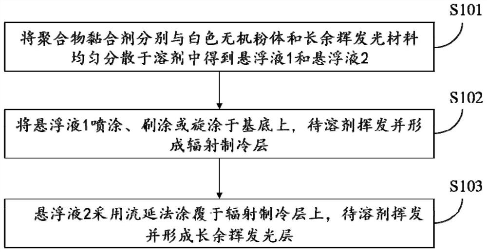
[0042] see figure 2 , figure 2 It is a flow chart of a preparation method of a radiation refrigeration coating with long afterglow luminescence provided by the present invention, such as figure 2 As shown, the preparation method includes:

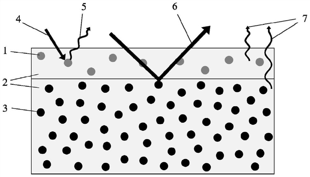
[0043] S101: uniformly dispersing the polymer binder, the white inorganic powder and the long afterglow luminescent material in a solvent to obtain suspension 1 and suspension 2;

[0044] S102: spraying, brushing or spin-coating the suspension 1 on the substrate, and waiting for the solvent to volatilize and form a radiation refrigeration layer;

[0045] S103: Coat the suspension 2 on the radiation refrigeration layer by a casting method, and wait for the solvent to volatilize to form a long afterglow luminescent layer.

[0046] In some embodiments, the method for uniform dispersion is treatment in a homogenizer for 30 minutes. The solvent is one or both of water, ethanol, toluene and acetone. The solvent volume fraction in the susp...

Embodiment 1

[0050] The long afterglow light-emitting layer in the coating described in this embodiment includes (SrAl 2 O 4 :Eu 2+ ,Dy 3+ ) and PMMA, the radiative cooling layer includes BaSO 4 and PVB. Among them, (SrAl 2 O 4 :Eu 2+ ,Dy 3+ ) with an average particle size of 0.1 μm, BaSO 4 The average particle size is 0.5 μm, tested with BaSO alone 4 The reflectance of the powder in the visible light band is 0.97. The thickness of the radiation cooling layer is about 500 μm, and the thickness of the long afterglow light-emitting layer is about 1 μm.

[0051] The coating preparation process is as follows: According to BaSO 4 : The mass ratio of PVB was 15:1, and it was mixed into the solvent, and then treated with a homogenizer for 30 min to obtain a uniform suspension 1. The volume fraction of the solvent in the suspension is 80%; the solvent is ethanol. The suspension 1 was sprayed on a glass plate with a spray gun, and was left to dry naturally at room temperature for 3 hou...

Embodiment 2

[0055] The long afterglow light-emitting layer in the coating described in this embodiment includes (Sr 2 MgSi 2 O 7 :Eu 2+ ,Dy 3+ ) and PMMA, the radiative cooling layer includes TiO 2 and TPX. Among them, (Sr 2 MgSi 2 O 7 :Eu 2+ ,Dy 3+ ) with an average particle size of 0.1 μm, TiO 2 The average particle size is 0.5 μm. The thickness of the radiation cooling layer is about 500 μm, and the thickness of the long afterglow light-emitting layer is about 2 μm.

[0056] The coating preparation process is as follows: According to TiO 2 : The mass ratio of TPX was 10:1, and it was mixed into the solvent, and then treated with a homogenizer for 30 min to obtain a uniform suspension 1. The volume fraction of the solvent in the suspension is 80%; the solvent is 50% water and 50% ethanol. The suspension 1 was sprayed on a glass plate with a spray gun, and was left to dry naturally at room temperature for 3 hours to form a radiation refrigeration layer with a thickness of a...


PUM

PropertyMeasurementUnit
thicknessaaaaaaaaaa
thicknessaaaaaaaaaa
particle diameteraaaaaaaaaa

Abstract

The invention belongs to the field of new materials, and more specifically relates to a radiation cooling coating with long afterglow luminescence performance and a preparation method thereof. The coating includes a radiative cooling layer, and also includes a long afterglow luminous layer arranged on the surface of the radiative cooling layer; the radiative cooling layer realizes cooling through heat radiation in the mid-infrared band range and light reflection in the visible light band range at the same time The long afterglow luminescent layer contains long afterglow luminescent materials, the absorption peak of the long afterglow luminescent material is between the sunlight bands, and the emission peak is between the visible light bands; when in use, the long afterglow luminescent layer absorbs sunlight energy and converts it It is visible light that is easily reflected by the radiation cooling layer, thereby reducing the energy absorbed by the radiation cooling layer and improving the radiation cooling power of the radiation cooling layer; on the other hand, the energy reflected by the radiation cooling layer is further illuminated by the long afterglow The layer absorbs and emits light, thereby improving the luminous efficiency of the long-lasting light-emitting layer.

Description

technical field [0001] The invention belongs to the field of new materials, and more particularly relates to a radiation refrigeration coating with long afterglow luminescence properties and a preparation method thereof. Background technique [0002] The two major problems of global warming and energy crisis are becoming more and more serious and affecting people's lives. In recent years, radiation refrigeration technology, which can alleviate the above two problems at the same time, has gradually emerged. [0003] Radiation refrigeration technology is a zero-energy-consumption refrigeration technology, which means that the heat source realizes heat exchange with the outer space cold source (~3K) through the infrared window of the atmosphere in the form of thermal radiation. Radiation refrigeration technology is of great significance for environmental protection and cooling energy saving. The specific principle of radiation cooling is: on the one hand, the surface of the m...

Claims


Application Information

Patent Timeline
Patent Type & Authority Patents(China)
IPC IPC(8): C09D5/22C09D133/12C09D129/14C09D201/00C09D127/18C09D123/08C09D127/16
CPCC09D5/22C09D133/12C09D129/14C09D201/00C09D127/18C09D123/0869C09D127/16C08K2003/3045C08K2003/2241C08K2003/265C08K2003/2227C08K3/24C08K3/30C08K3/22C08K3/34C08K3/26C08K3/36Y02P20/10
Inventor 刘沛赵晓阳李晓琼周东炜段将将
Owner HUAZHONG UNIV OF SCI & TECH
Why Eureka
Try Eureka