Low-carbon energy utilization system for oil field steam-electricity co-production

An oil field and energy technology, applied in steam applications, electrical components, circuit devices, etc., can solve the problems of large fluctuations in steam sources, large land occupation, high investment and maintenance costs, etc., to achieve strong peak-shaving capabilities, reduce carbon dioxide emissions, and ensure thick The effect of oil production

Pending Publication Date: 2021-06-15
TSINGHUA UNIV +1
View PDF0 Cites 0 Cited by
  • Summary
  • Abstract
  • Description
  • Claims
  • Application Information

AI Technical Summary

Problems solved by technology

[0005] The existing solar thermal conversion steam injection technology mainly has the following disadvantages and shortcomings: 1) The thermal efficiency of solar thermal conversion is unbalanced: due to the characteristics of strong periodicity and large uncertainty of solar energy, simply using it to produce steam will cause fluctuations in steam sources Big problem, unable to meet the needs of heavy oil production
2) High investment and maintenance costs: The investment cost of solar thermal energy exceeds 10,000 yuan / kW, the maintenance cost of thermal fluid pipelines is high, and the cost of steam production is too high, which cannot be afforded by oil field users
3) CSP power generation occupies a large area: CSP power stations need to occupy a large amount of land and lay complex pipelines. In actual oil fields, a large number of oil production pipelines have been laid, and it is impossible to lay light fields and thermal pipelines at low cost.
4) Lack of industrial projects in actual operation: Based on the two main reasons of unbalanced thermal efficiency and insufficient economy, the application of solar thermal conversion heavy oil thermal recovery technology has no actual industrial projects in operation in China, and is still in the research and design stage

Method used


Image

  • Low-carbon energy utilization system for oil field steam-electricity co-production

Examples


Embodiment Construction

[0034] Embodiments of the present invention are described in detail below, examples of which are shown in the drawings, wherein the same or similar reference numerals designate the same or similar elements or elements having the same or similar functions throughout. The embodiments described below by referring to the figures are exemplary only for explaining the present invention and should not be construed as limiting the present invention.

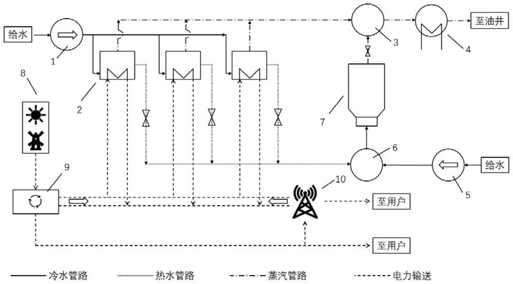
[0035] Combine below figure 1 A low-carbon energy utilization system for cogeneration of gas and electricity in an oil field according to an embodiment of the present invention will be described.

[0036] Such as figure 1As shown, the low-carbon energy utilization system for oil field cogeneration of steam and electricity according to the embodiment of the present invention includes a first water pump device 1, a second water pump device 5, an electric heating device 2, a liquid mixer 6, and a fossil fuel steam injection furnace 7 , st...


PUM


Abstract

The invention discloses a low-carbon energy utilization system for oil field steam-electricity co-production. The low-carbon energy utilization system comprises a first water pump device, a second water pump device, electric heating equipment, a liquid mixer, a fossil fuel steam injection furnace, a steam mixer, a superheater and a new energy power station, wherein the electric heating equipment is connected with the first water pump device; the liquid mixer is respectively connected with the second water pump device and the electric heating equipment; the fossil fuel steam injection furnace is connected with the liquid mixer; the steam mixer is respectively connected with the electric heating equipment and the fossil fuel steam injection furnace; the superheater is connected with the steam mixer; and the new energy power station is used for providing power for the electric heating equipment. Low-carbon clean energy such as light energy and wind energy in an oil field area is cooperatively utilized to achieve oil field steam-electricity co-production, and the purposes of solving the wind and electricity abandoning problem and achieving oil field low-carbon heavy oil thermal recovery are achieved at the same time.

Description

technical field [0001] The invention relates to the technical field of comprehensive utilization of low-carbon energy in oilfields, in particular to a low-carbon energy utilization system for cogeneration of steam and electricity in oilfields. Background technique [0002] With the proposal of my country's "30 carbon peak and 60 zero carbon emission" strategy, energy saving and carbon reduction have become an important issue in the field of energy production and consumption. The oil field is a major producer of energy and steam for industrial use, especially in the process of mining heavy oil, it is necessary to use a large amount of fossil fuels to produce steam to extract heavy oil. For every ton of heavy oil extracted, 8 tons of steam are required, which will consume about 0.8 tons of raw coal and about 500 One cubic meter of natural gas corresponds to the emission of 1 to 2 tons of carbon dioxide, which brings great pressure to reduce carbon emissions in heavy oil produc...

Claims


Application Information

Patent Timeline
Patent Type & Authority Applications(China)
IPC IPC(8): F01K13/00F01K13/02F01K27/00F01K17/02F01K21/00
CPCF01K13/00F01K13/02F01K27/00F01K17/02F01K21/00Y02E20/14H02J3/381H02J2300/10H02J2300/20F22B33/18E21B43/24F22B1/28
Inventor 吴玉新刘琦吕俊复张缦张扬黄中周托刘青
Owner TSINGHUA UNIV
Why Eureka
Try Eureka