Clutch device

A clutch device and clutch technology, applied in the clutch field, can solve the problems of failure of the separation system, blockage of the oil inlet hole of the performance of the separation system, etc.

Pending Publication Date: 2021-06-15
SCHAEFFLER TECH AG & CO KG
View PDF1 Cites 0 Cited by
  • Summary
  • Abstract
  • Description
  • Claims
  • Application Information

AI Technical Summary

Problems solved by technology

This contact creates a load in the separation system which can negatively affect the performance of the separation system, for example the position of the slave cylinder piston will change and the oil inlet holes may become blocked, eventually leading to failure of the separation system

Method used


Image

  • Clutch device

Examples


Embodiment Construction

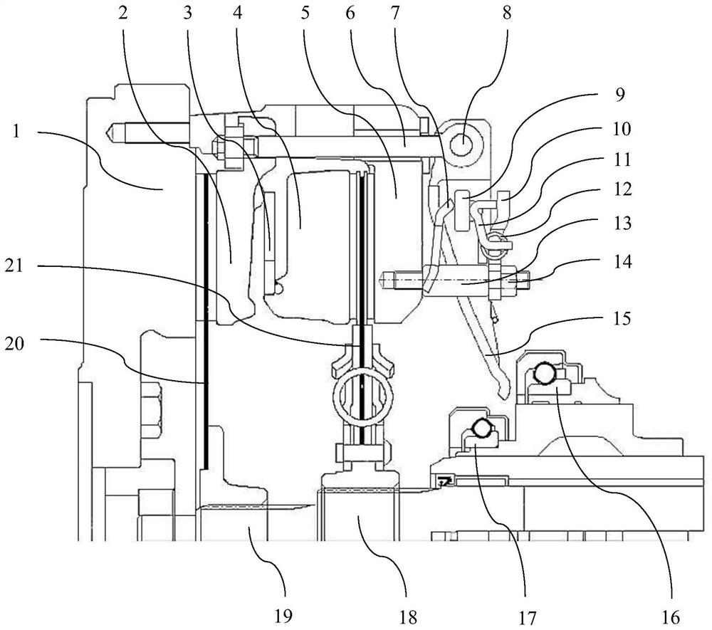
[0026] figure 1 A schematic half-sectional view of a clutch device embodied according to a preferred embodiment is shown. In this embodiment, the clutch device is designed as a dual clutch device for a tractor. The double clutch device includes a clutch housing 5, two friction clutches and actuating mechanisms respectively corresponding to the two friction clutches.

[0027] In the present embodiment, two friction clutches, a first clutch and a second clutch, are used to selectively transmit torque generated by the engine, respectively. The first clutch selectively connects the engine with the drive. A second clutch selectively connects the engine and the auxiliary drive. Here, the first clutch is closer to the engine than the second clutch.

[0028] The first clutch includes a counter pressure plate 1 , a pressure plate 2 and a friction disc 20 arranged between the counter pressure plate 1 and the pressure plate 2 . In this case, the counterplate 1 is connected in a rota...


PUM


Abstract

The invention relates to a clutch device, in particular a dual clutch device. The clutch device comprises a clutch housing (5) for introducing a torque into the clutch device, a friction clutch and an actuating mechanism. The friction clutch is used for selectively transmitting torque at the clutch housing (5). The actuating mechanism is used for operating the friction clutch and comprises an actuating rod (6) and an actuating lever (15), the actuating rod (6) is able to act on a pressure plate (2) of the friction clutch, the actuating rod (6) and the actuating lever (15) can be connected to each other so as to be rotatable relative to each other, the actuating lever (15) is supported on the clutch housing (5) so as to be rotatable relative to the clutch housing (5). The clutch device further comprises a sensing spring (7) and a wear compensation assembly, so that when wear occurs in the friction clutch, the wear compensation assembly is able to act on the actuating lever (15) to adjust the position of the actuating lever (15).

Description

technical field [0001] The invention relates to the technical field of clutches. The invention relates in particular to a clutch arrangement for a vehicle, in particular a tractor. Background technique [0002] In a clutch arrangement concept for a tractor, the clutch arrangement is designed as a double clutch arrangement with two friction clutches, one of which can selectively connect the engine to the travel drive, and the other clutch can selectively connect the engine and auxiliary drives. Such a clutch arrangement is disclosed, for example, in document EP 1 503 098 A1. In this type of solution, at least one clutch of the clutch arrangement is configured as a "normally closed" clutch. The clamping force of a "normally closed" clutch may be provided by a tension member in the form of a diaphragm spring. The opening of the clutch can be effected by means of a lever-like actuating lever. When the clutch is disengaged, this can be achieved by the action of the release b...

Claims


Application Information

Patent Timeline
Patent Type & Authority Applications(China)
IPC IPC(8): F16D13/38F16D13/58F16D13/75
CPCF16D13/38F16D13/58F16D13/75
Inventor 田帅范意中
Owner SCHAEFFLER TECH AG & CO KG
Why Eureka
Try Eureka