Laying equipment for heat distribution pipeline

A thermal pipeline and equipment technology, applied in the field of laying equipment for thermal pipeline installation, can solve problems such as increasing workload, affecting equipment reuse, soil falling, etc., and achieves the effects of quick cleaning, easy maintenance, and avoiding rupture

Inactive Publication Date: 2021-06-15
安徽省正大电力建设有限公司
View PDF0 Cites 0 Cited by
  • Summary
  • Abstract
  • Description
  • Claims
  • Application Information

AI Technical Summary

Problems solved by technology

When laying thermal pipelines, it is necessary to use machinery to dig out ditches on the ground, lay the pipelines inside, and bury them. The thermal pipelines directly buried in the soil require regular maintenance due to the complex laying environment. Secondary excavation is required before maintenance. In order to avoid damage to the pipeline, the working process around the pipeline is slow, which increases the workload, and the maintenance and inspection of the pipeline is inconvenient due to the soil at the bottom of the pipeline.
[0003] When maintaining the pipeline, it is necessary to clean up the soil around the pipeline at the maintenance point. When the existing laying equipment is in use, the soil on the upper end of the equipment cannot be cleaned. When the equipment is opened, the soil above is likely to fall into the equipment. It affects the re-use of the equipment, and when the laying equipment is in use, it has a certain fixing effect on the pipeline, and when the pipeline expands with heat and contracts with cold, it is easy to break because it is in the fixed section, which affects the use of the thermal pipeline

Method used


Image

  • Laying equipment for heat distribution pipeline
  • Laying equipment for heat distribution pipeline
  • Laying equipment for heat distribution pipeline

Examples


Embodiment 1

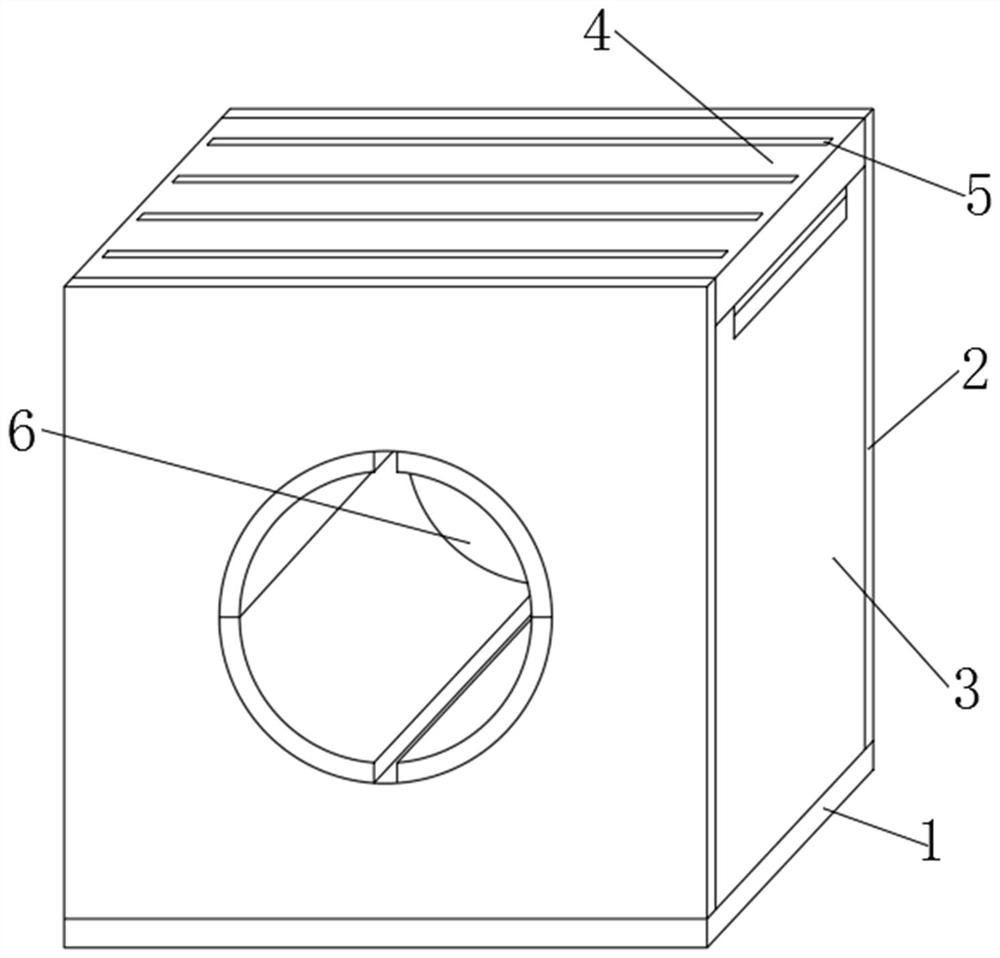
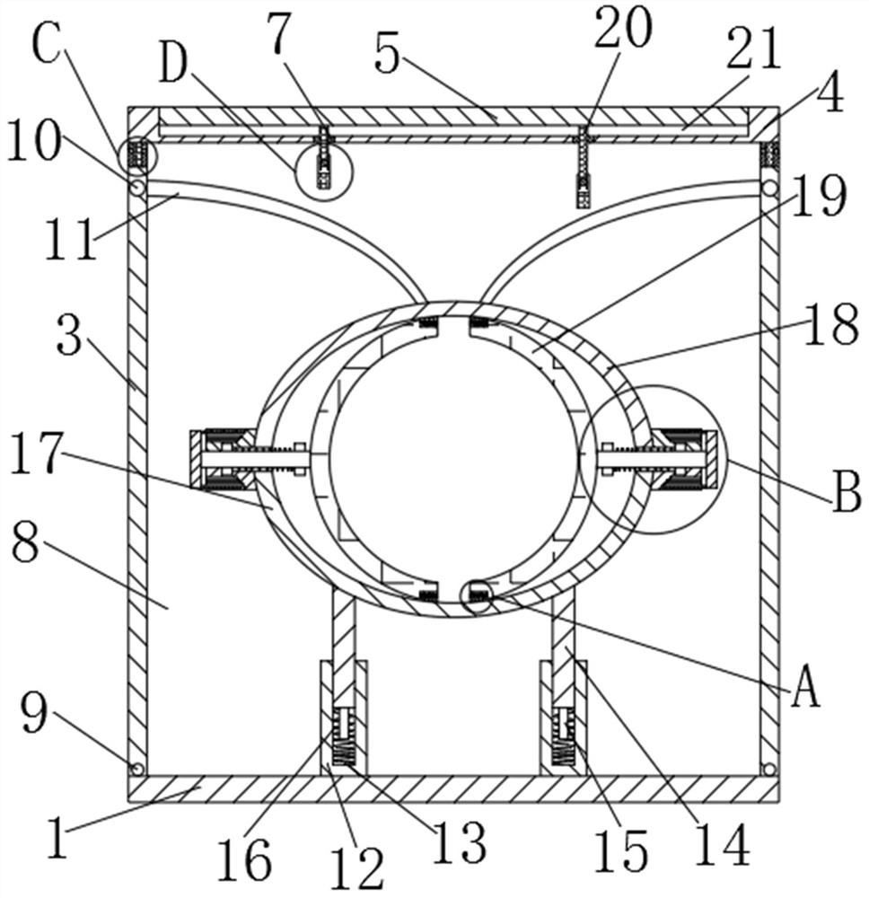
[0033] Such as Figure 1-6 As shown, a laying equipment for thermal pipelines includes a base 1, a vertical plate 2 is fixed on both sides of the upper surface of the base 1, and a mounting hole 6 is opened on the vertical plate 2, and the upper surface of the base 1 is The other two sides of the rotating plate 3 are provided with a rotating shaft 9 below the side of the rotating plate 3, and the two ends of the rotating shaft 9 are inserted into the vertical plates 2 on both sides, and the upper side of the vertical plate 2 is A limiting groove 11 is opened, and a limiting rod 10 is fixed above the two sides of the rotating plate 3, and the limiting rod 10 is inserted into the limiting groove 11. Turning plates 37 are arranged on both sides of the upper surface of the rotating plate 3, The turning plate 37 and the rotating plate 3 are rotationally connected by a fixed shaft 36, the upper end of the turning plate 37 is fixed with a compression member 38, and a cover plate 4 is...

Embodiment 2

[0037] A laying equipment for thermal pipelines, comprising a base 1, a vertical plate 2 is fixed on both sides of the upper surface of the base 1, and an installation hole 6 is opened on the vertical plate 2, and the other two on the upper surface of the base 1 The side is provided with a rotating plate 3, the bottom of the rotating plate 3 side is provided with a rotating shaft 9, the two ends of the rotating shaft 9 are inserted into the vertical plates 2 on both sides, the base 1, the vertical plate 2 and the rotating plate 3 to form a cavity 8, the upper surface of the base 1 is fixed with two groups of bottom plates 12, the upper surface of the bottom plate 12 is provided with a vertical groove 13, and a movable plate 14 is inserted in the vertical groove 13, and the movable plate 14 is inserted into the vertical groove 13. Several sets of sleeve rods 15 are fixed on the lower surface of the plate 14 , and first springs 16 are sleeved on the sleeve rods 15 .

[0038] The...

Embodiment 3

[0046] A method for using laying equipment for thermal pipelines, the specific steps are as follows:

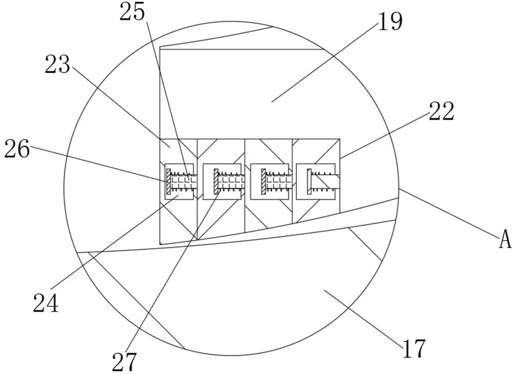
[0047] Step 1: Place the device at the maintenance place, and move the clip 19 to both sides by pulling the first fixing plate 29. When the pipe passes through the installation hole 6, loosen the first fixing plate 29 so that the clip 19 is at the Under the action of the three springs 30, it is closely attached to the surface of the pipeline, and with the action of the third spring 30, the clamping plate 35 is inserted into the corresponding fixing groove 34, and the inserting plates 39 on both sides of the lower surface of the cover plate 4 are inserted and turned over. between plates 37;

[0048] Step 2: When it is necessary to maintain the pipeline, clean up the soil around the device. When only cleaning the soil around the device, because the device is not within the scope of cleaning, the cleaning is relatively fast. When cleaning the soil above the device, the The lowe...


PUM


Abstract

The invention relates to laying equipment for a heat distribution pipeline, comprising a base. Vertical plates are fixed to the two sides of the upper surface of the base; rotating plates are arranged on the other two sides of the upper surface of the base; limiting grooves are formed in the upper portions of the side faces of the vertical plates; limiting rods are fixed to the upper portions of the two side faces of each rotating plate; overturning plates are arranged on the two sides of the upper surfaces of the rotating plates; cover plates are arranged above the rotating plates; inserting plates are fixed to the two sides of the lower surfaces of the cover plates; and a plurality of sets of top plates are embedded into the cover plates. The laying equipment has the beneficial effects that during inclination, the top plates arranged on the cover plates can be separated from the cover plates, and mud blocks bonded on the cover plates are stripped under the action of the top plates, so that rapid cleaning is achieved, and rapid maintenance is facilitated; a clamping member is extruded through expansion of a pipeline so as to move towards the two sides; and an upper fixed plate and a lower fixed plate are driven to move, so that the pipeline is always in a fixed state during expansion, and the pipeline is protected.

Description

technical field [0001] The invention relates to laying equipment for thermal pipelines, and belongs to the technical field of laying equipment for thermal pipeline installation. Background technique [0002] In recent years, with the increase in demand for heating, the distance and diameter of thermal pipelines installed in pipe galleries and tunnels has continued to increase, and the safety and stability of the pipeline network have received more and more attention. Also known as the heat pipe network, starting from the boiler room, direct-fired machine room, heating center, etc., the heat supply pipes from the heat source to the heat entrance of the building, in the process of transportation, the heat pipes need to be arranged over a long distance to be transported from the heat supply center to the required location. When laying thermal pipelines, it is necessary to use machinery to dig out ditches on the ground, lay the pipelines inside, and bury them. The thermal pipel...

Claims


Application Information

Patent Timeline
Patent Type & Authority Applications(China)
IPC IPC(8): F16L1/06F16L57/00
CPCF16L1/06F16L57/00
Inventor 孙子亿
Owner 安徽省正大电力建设有限公司
Why Eureka
Try Eureka