Beef ball stringing equipment for food processing
A technology for food processing and beef balls, applied in meat processing equipment, processing meat, skewering meat onto skewers, etc., can solve the problems of high cost, inconsistent beef ball skewers, slow time, etc. Time, easy to collect in bunches, convenient and fast blanking effect
- Summary
- Abstract
- Description
- Claims
- Application Information
AI Technical Summary
Problems solved by technology
Method used
Image
Examples
Embodiment 1
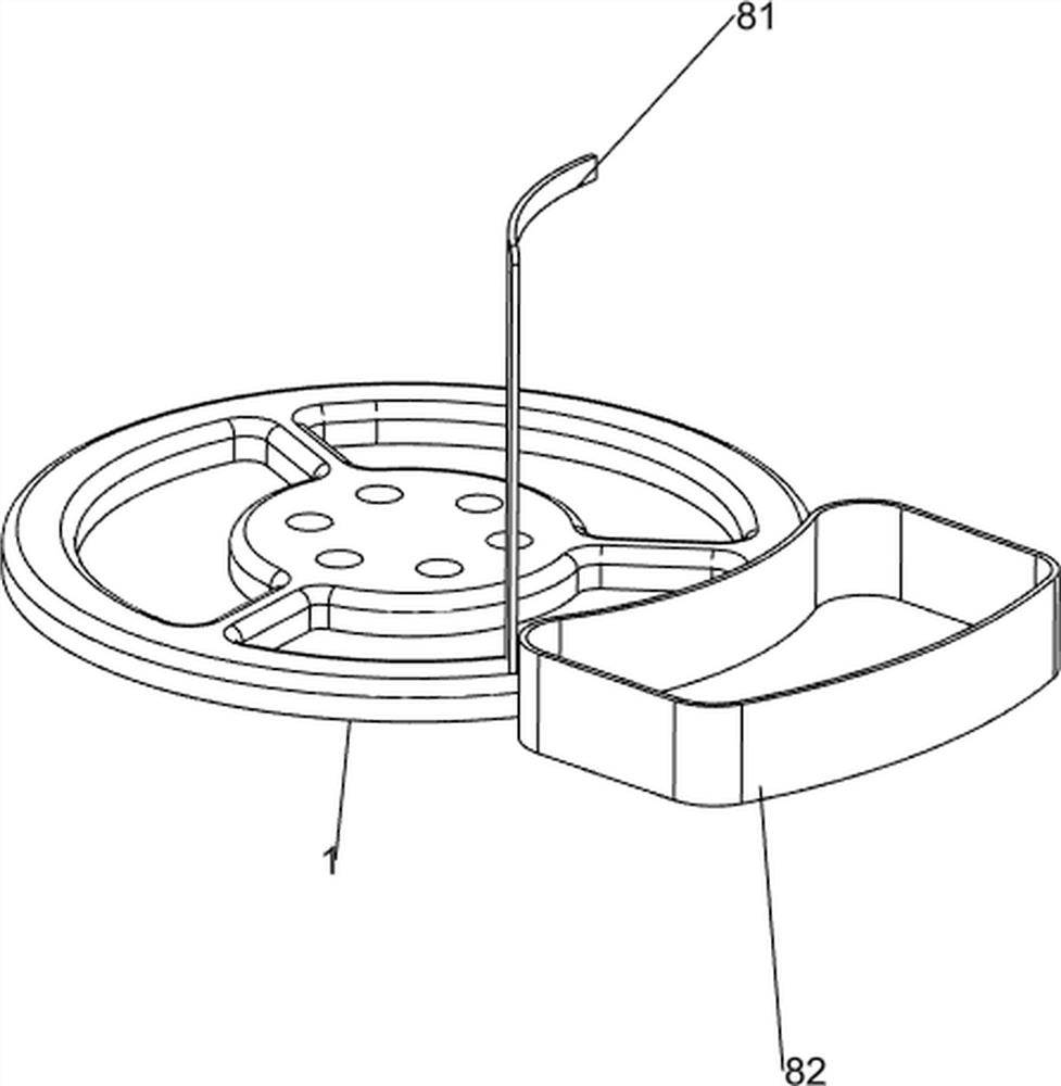
[0067] A kind of equipment for stringing beef balls for food processing, such as figure 1 As shown, it includes a base 1, a support frame 2, a pressing mechanism 3, a rotating mechanism 4 and a reloading mechanism 5. A rotating mechanism 4 is arranged between the pressing mechanism 3 , and a transfer mechanism 5 is arranged between the base 1 and the rotating mechanism 4 .
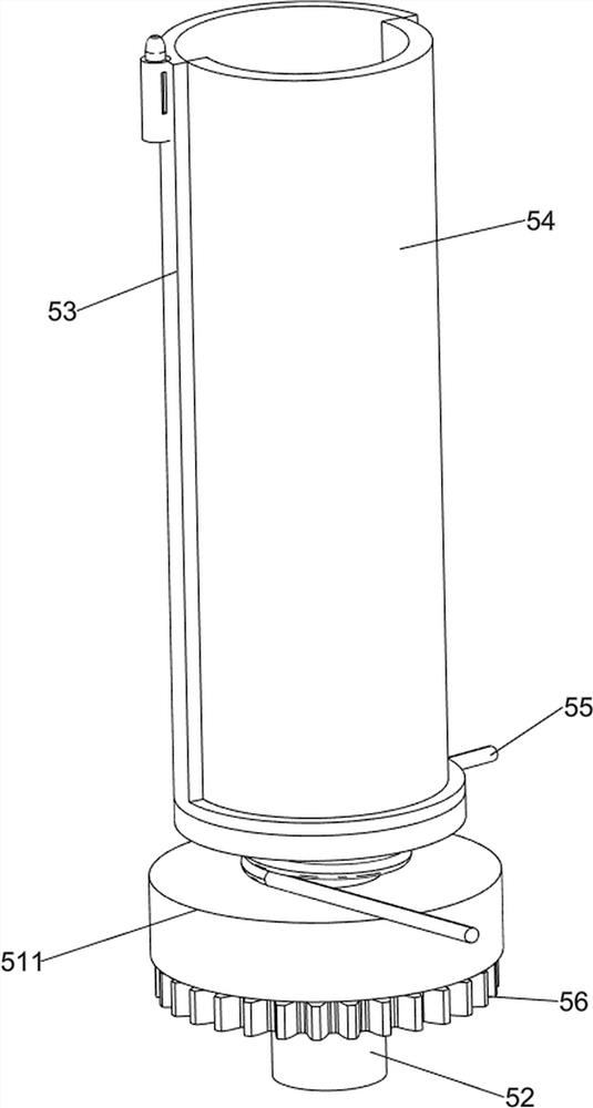
[0068]When people need to string the beef balls, they place the beef balls in the reloading mechanism 5, and then people open the pressing mechanism 3, so that the pressing mechanism 3 cooperates with the rotating mechanism 4, and then drives the rotating mechanism 4 to rotate, so that The reprinting mechanism 5 rotates, and now people insert the bamboo sticks into the beef balls, so that people collect the stringed beef balls through the reprinting mechanism 5, and when people need to string the beef balls, they place the beef balls on the reloading In the mechanism 5, when people do not need to string t...
Embodiment 2
[0070] On the basis of Example 1, such as figure 2 As shown, the pressing mechanism 3 includes a cylinder 31, a fixed connection block 32 and a straight rack 33, the top of the support frame 2 is equipped with a cylinder 31, the telescopic rod of the cylinder 31 is connected with a fixed connection block 32, and the bottom of the fixed connection block 32 is provided with Straight rack 33.
[0071] When people place the beef balls in the reload mechanism 5, people open the cylinder 31, so that the telescopic rod of the cylinder 31 drives the fixed connection block 32 to move, and when the telescopic rod of the cylinder 31 drives the fixed connection block 32 to move downward, the The spur rack 33 moves downwards. At this time, the spur rack 33 does not cooperate with the rotating mechanism 4. When the telescopic rod of the cylinder 31 drives the fixed connection block 32 to move upward, the spur rack 33 moves upward. At this time, the spur rack 33 Cooperating with the rotati...
Embodiment 3
[0073] On the basis of Example 2, such as figure 1 , image 3 , Figure 4 , Figure 5 , Image 6 , Figure 7 , Figure 8 with Figure 9 As shown, the rotating mechanism 4 includes a first bracket 41, a rotating shaft 42, a rotating disk 43, a bearing 44, a first transmission shaft 45, a first full gear 46 and a bevel gear set 47, and the rear side of the base 1 is provided with a first bracket 41, the upper middle part of the base 1 is provided with a rotating shaft 42, the middle part of the rotating shaft 42 is provided with a bearing 44, the bearing 44 is provided with a rotating disk 43, and the first support 41 is provided with a first transmission shaft 45 in a rotational manner, and the first transmission shaft 45 A first full gear 46 is provided on the upper left side, and the first full gear 46 meshes with the spur rack 33 , and a bevel gear set 47 is provided between the rotating shaft 42 and the first transmission shaft 45 .
[0074] When the spur rack 33 mov...
PUM
 Abstract
Description
Claims
Application Information
 - R&D
- Intellectual Property
- Life Sciences
- Materials
- Tech Scout
- Unparalleled Data Quality
- Higher Quality Content
- 60% Fewer Hallucinations
Browse by: Latest US Patents, China's latest patents, Technical Efficacy Thesaurus, Application Domain, Technology Topic, Popular Technical Reports.
© 2025 PatSnap. All rights reserved.Legal|Privacy policy|Modern Slavery Act Transparency Statement|Sitemap|About US| Contact US: help@patsnap.com


