
Bolt following rotation preventing device

A technology of bolts and shafts, applied in the field of bolt anti-rotation devices, which can solve the problems of high labor intensity, increased production costs, and high manufacturing costs

Inactive Publication Date: 2021-06-18
DONGFENG LIUZHOU MOTOR
View PDF16 Cites 1 Cited by
  • Summary
  • Abstract
  • Description
  • Claims
  • Application Information

AI Technical Summary

Problems solved by technology

[0006] 1. When manually using the extended wrench to clamp the bolt to prevent rotation, it is necessary to increase the number of operators who specialize in clamping the bolt to prevent rotation, thereby increasing the production cost; the safety hazard of pinching and injuring people is large; the labor intensity of the operation is high;
[0007] 2. When using a specially designed direct-drive electric constant-torque gun with non-standard tooling to prevent rotation, the overall structure of the direct-drive electric constant-torque gun is complex and the manufacturing cost is high; the direct-drive electric constant-torque gun is bulky and inconvenient to operate ;The direct-drive electric fixed torque gun has poor versatility, and it is very easy to interfere with the workpiece and cannot be used; in the process of use, it is impossible to avoid the safety hazard of pinching hands and hurting people

Method used


Image

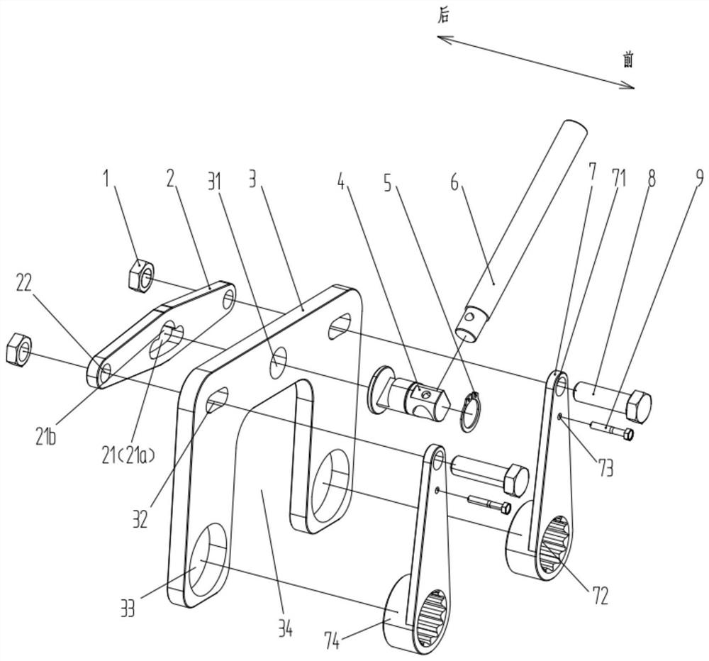
  • Bolt following rotation preventing device
  • Bolt following rotation preventing device
  • Bolt following rotation preventing device

Examples


Embodiment Construction

[0033] The specific implementation manners of the present invention will be further described in detail below in conjunction with the accompanying drawings and embodiments. The following examples are used to illustrate the present invention, but are not intended to limit the scope of the present invention. Apparently, the described embodiments are only some of the embodiments of the present invention, but not all of them. Based on the embodiments of the present invention, all other embodiments obtained by persons of ordinary skill in the art without creative efforts fall within the protection scope of the present invention.

[0034] It should be understood that the terms "first", "second", etc. are used in the present invention to describe various information, but these information should not be limited to these terms, and these terms are only used to distinguish information of the same type from each other. For example, "first" information may also be referred to as "second"...


PUM


Abstract

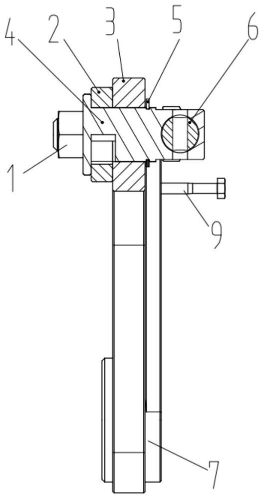
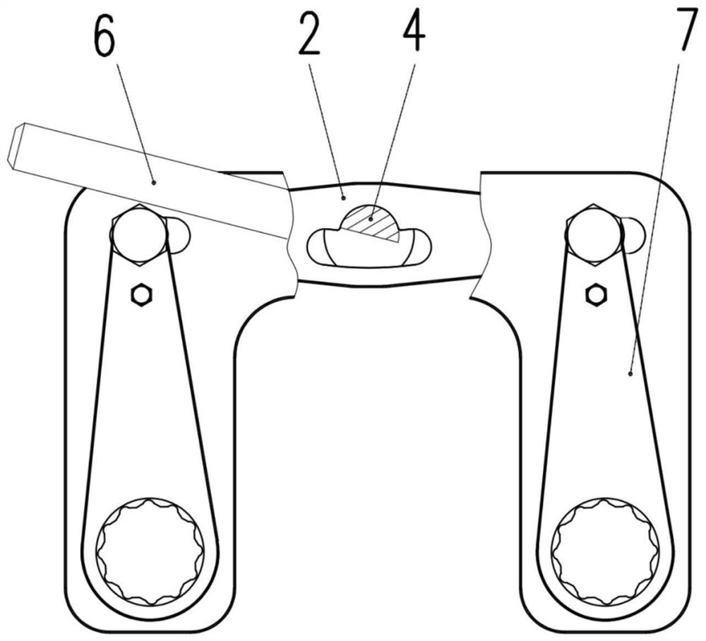
The invention relates to the technical field of locking devices, and discloses a bolt following rotation preventing device which comprises a sliding plate, a mounting plate and two plate sleeves. The plate sleeves are provided with sleeved connection parts, sleeve holes are formed in the sleeved connection parts, mounting holes and sliding grooves are formed in the mounting plate, the sleeved connection parts are inserted into the mounting holes, fixing pieces are inserted into the sliding grooves, the fixing pieces can slide along the sliding grooves, the fixing pieces are connected with the plate sleeves and the sliding plate, a clamping groove is formed in the sliding plate, and a limiting hole is formed in the position, corresponding to the clamping groove, of the mounting plate. A rotating shaft sequentially penetrates through the clamping groove and the limiting hole, the two ends of the rotating shaft are connected with the sliding plate and the mounting plate correspondingly, the clamping groove is provided with a limiting part and an unloading part which communicate with each other, the unloading part communicate extends towards the two sides of the limiting part, the rotating shaft is provided with an abutting connection part connected with the limiting part, the abutting connection part and the limiting part can be disconnected or connected by driving the rotating shaft to rotate, and the abutting connection part is connected in the unloading part in a sliding manner. According to the technical scheme, the bolt following rotation preventing device can avoid bolt following rotation, and the potential safety hazards that hands are pinched and people are hurt are avoided.

Description

technical field [0001] The invention relates to the technical field of locking devices, in particular to a bolt anti-rotation device. Background technique [0002] At present, the direct-drive electric constant torque gun has been widely used in various bolt and nut tightening occasions due to its advantages of high-precision torque control and intelligence. The through-bolt connection structure (bolt holes are smooth holes, which need to be tightened with bolts and nuts at the same time) is widely used in various assembly occasions such as automobile assembly. Because of the working principle of the direct drive electric constant torque gun, when the nut is tightened with the direct drive electric constant torque gun, the bolt will rotate, and it takes a lot of torque to clamp the bolt to prevent the rotation, which cannot be used by hand. The wrench clamps the bolt to prevent rotation. In order to prevent the bolt from rotating, two methods are generally adopted: [000...

Claims


Application Information

Patent Timeline
IPC IPC(8): B25B27/14
CPCB25B27/143
Inventor 黄勇赵卿覃政区锦文白林
Owner DONGFENG LIUZHOU MOTOR
Learn More