
A Compensation Method for Inertial Force of Robot

A compensation method and robot technology, applied in manipulators, program-controlled manipulators, manufacturing tools, etc., can solve problems such as large calculation errors and large inertial force errors, and achieve the effect of eliminating influence, concise form and smooth motion.

Active Publication Date: 2022-03-11
NANJING UNIV OF AERONAUTICS & ASTRONAUTICS
View PDF8 Cites 0 Cited by
  • Summary
  • Abstract
  • Description
  • Claims
  • Application Information

AI Technical Summary

Problems solved by technology

[0004] The traditional inertial mass of the load end is obtained by integral calculation based on the rigid body shape and material of the robot end effector (including sensors and fixtures) using theoretical mechanics theory. When the overall shape of the actuator is relatively regular, the calculation result is more accurate, but usually , the actuator is assembled from a number of different parts, and the materials of each part are also quite different, resulting in a large calculation error in the inertial mass M of the actuator; therefore, the M obtained by theoretical calculation is multiplied by the acceleration value a measured by the sensor The error of the obtained inertial force is also relatively large, so in order to meet the requirements of machining contact force measurement accuracy, a robot inertial force compensation method is urgently needed to solve the above problems

Method used


Image

  • A Compensation Method for Inertial Force of Robot
  • A Compensation Method for Inertial Force of Robot
  • A Compensation Method for Inertial Force of Robot

Examples


Embodiment

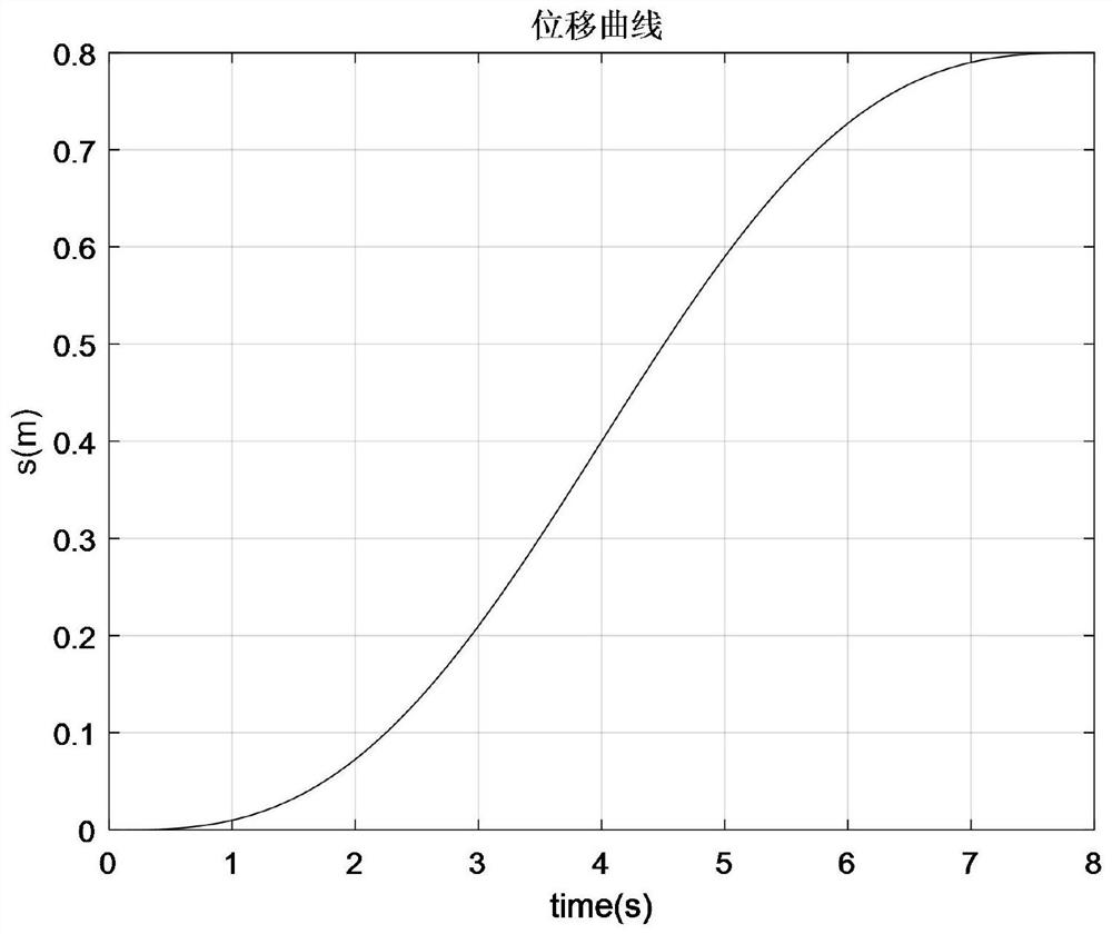
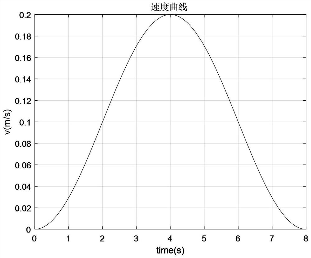
[0045] Example: such as figure 1 As shown, a robot inertial force compensation method, by measuring the inertial force and using the measured acceleration, establishes the mapping relationship between the inertial force and the acceleration, so as to accurately compensate the inertial force, including:

[0046] S1. Obtain the acceleration, including planning the end of the robot to move in a straight line, and determine its starting point and end point, and establish the parameter equation of the motion trajectory as Sampling all time step points in the linear motion, and calculating the acceleration a(t) of all time step points;

[0047] First, determine the starting point of the linear motion of the end of the robot Ps=(x s ,y s ,z s ) and end point Pe=(x e ,y e ,z e ), calculate the straight-line distance between them as Determine the total time of the linear motion of the end of the robot as T, wherein the distance between the two points is located in the working s...


PUM


Abstract

The invention discloses a method for compensating inertial force of a robot, which includes obtaining acceleration, obtaining inertial force, and establishing a mapping between inertial force and acceleration: F inert =[M]·a, calculate the inertia force compensation parameter [M], let the compensation force F comp =‑F inert , compensation torque T comp =‑T inert , used for inertial force compensation with load measurement, in which, by letting the end of the robot move in a straight line and establishing a linear motion trajectory parameter equation, the form is simple and easy to implement. At the same time, the acceleration changes according to the sinusoidal law, and the measurement is efficient and simple, ensuring the movement. Smooth and easy to control; In addition, by measuring the inertial force F inert , using the measured acceleration a, the mapping relationship between inertial force and acceleration is established, so as to accurately compensate the inertial force, improve real-time calculation efficiency, and do not need to measure the shape and material of the end effector of the robot, avoiding the integral calculation of rotation Inertia complexity and calculation errors.

Description

technical field [0001] The invention relates to the technical field of robot processing, in particular to a robot inertial force compensation method. Background technique [0002] The machining accuracy of the robot is closely related to its acceleration and deceleration motion control and dynamics control. At present, when industrial robots are used in processing, assembly and other industries, the contact force between the end tool or workpiece of the robot and the external environment needs to be accurately sensed to ensure the flexibility of the operation. In existing applications, a six-component force sensor is usually selected, which can measure three-dimensional orthogonal force, three-dimensional orthogonal moment, three-dimensional orthogonal acceleration, and three-dimensional orthogonal angular acceleration in any force system in space; under dynamic conditions, the robot end The torque measured by the sensor includes the weight of the load, the inertial force o...

Claims


Application Information

Patent Timeline
Patent Type & Authority Patents(China)
IPC IPC(8): B25J9/16
CPCB25J9/1638
Inventor 段晋军戴振东刘正权郭策
Owner NANJING UNIV OF AERONAUTICS & ASTRONAUTICS
Learn More