
Thrust wheel shaft, thrust wheel and operation machine

A technology of a roller shaft and a roller, which is applied in the fields of rollers, operating machinery, and roller shafts, can solve the problems of improving the lubrication environment of the floating oil seal that cannot be used for rollers, and the simple structure of roller shafts, and achieves a good performance. Lubrication and cooling effect, improve the lubrication environment, ensure the effect of service life

Active Publication Date: 2021-06-18
SANY HEAVY MACHINERY
View PDF9 Cites 6 Cited by
  • Summary
  • Abstract
  • Description
  • Claims
  • Application Information

AI Technical Summary

Problems solved by technology

[0005] The invention provides a supporting wheel shaft, a supporting wheel and an operating machine, which are used to solve the problem that the existing supporting wheel shaft has a simple structure and cannot improve the lubricating environment of the floating oil seal of the supporting wheel

Method used


Image

  • Thrust wheel shaft, thrust wheel and operation machine
  • Thrust wheel shaft, thrust wheel and operation machine
  • Thrust wheel shaft, thrust wheel and operation machine

Examples


Embodiment Construction

[0032] In order to make the purpose, technical solutions and advantages of the present invention clearer, the technical solutions in the present invention will be clearly and completely described below in conjunction with the accompanying drawings in the present invention. Obviously, the described embodiments are part of the embodiments of the present invention , but not all examples. Based on the embodiments of the present invention, all other embodiments obtained by persons of ordinary skill in the art without creative efforts fall within the protection scope of the present invention.

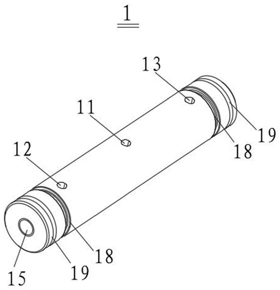
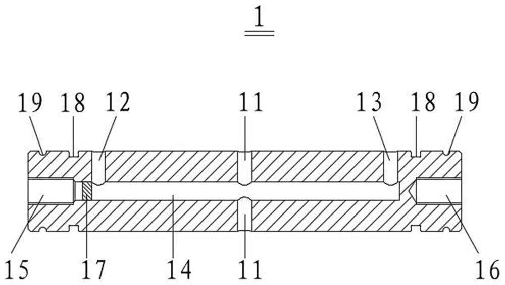
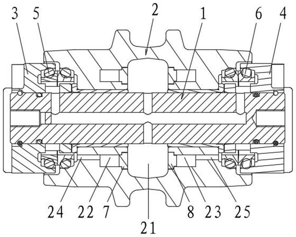
[0033] Combine below Figure 1-Figure 4 A track roller axle, track roller and working machine of the present invention are described.

[0034] Such as Figure 1 to Figure 2 As shown, the present embodiment provides a roller shaft, and the roller shaft 1 includes: an oil inlet 11, a first oil outlet 12, a second oil outlet 13 and a lubricating oil passage 14; the oil inlet 11 is provided Ne...


PUM


Abstract

The invention provides a thrust wheel shaft, a thrust wheel and an operation machine. The thrust wheel shaft comprises an oil inlet, a first oil outlet, a second oil outlet and a lubricating oil channel. The oil inlet is formed near the middle part of the thrust wheel shaft and is used for communicating with a first oil storage cavity on a wheel body of the thrust wheel; the first oil outlet is formed in the first end close to the thrust wheel shaft and used for extending to a first floating oil seal on the thrust wheel. The second oil outlet is formed in the second end close to the thrust wheel shaft and is used for extending to a second floating oil seal on the thrust wheel; the lubricating oil channel is arranged in the supporting wheel shaft and extends from the first end of the supporting wheel shaft to the second end of the supporting wheel shaft, and the lubricating oil channel is communicated with the oil inlet, the first oil outlet and the second oil outlet. The lubricating environment of the floating oil seal of the thrust wheel is improved, the situation that the floating oil seal and a lining of the thrust wheel are excessively abraded due to the fact that the lubricating oil amount is reduced is prevented, and the service life of the thrust wheel is guaranteed.

Description

technical field [0001] The invention relates to the technical field of operating machinery, in particular to a support wheel shaft, a support wheel and an operating machine. Background technique [0002] In working machinery, supporting rollers are widely used as chassis bearing parts of crawler excavators, cranes and other working machinery. Due to the large working load of the track rollers, and the working machinery often works in the environment with poor conditions such as muddy water and dust, impurities such as cement and dust can easily enter the track rollers, resulting in damage to the track rollers. Among them, the damage of the roller is mainly reflected in the oil leakage of the floating oil seal of the roller. [0003] Existing rollers usually include a wheel body and a roller shaft. The wheel body is rotatably sleeved on the roller shaft. Realize the communication of the cavities where the floating oil seals on the left and right sides of the rollers are loc...

Claims


Application Information

Patent Timeline
Patent Type & Authority Applications(China)
IPC IPC(8): B62D55/15
CPCB62D55/15B62D55/092B62D55/088F16J15/441
Inventor 胡小康孙传东成忠威
Owner SANY HEAVY MACHINERY
Learn More