
Valve special for pneumatic conveying

A pneumatic conveying and valve technology, which is used in conveyors, conveying bulk materials, transportation and packaging, etc. It can solve the problems of operator hand burns, gas operator hand contact, and low safety.

Pending Publication Date: 2021-06-18
ZHEJIANG GUTE PNEUMATIC MACHINERY
View PDF1 Cites 0 Cited by
  • Summary
  • Abstract
  • Description
  • Claims
  • Application Information

AI Technical Summary

Problems solved by technology

[0007] In order to solve the above technical problems, the present invention provides a special valve for pneumatic conveying to solve the existing problem that the existing device cannot improve the sealing performance of the piston and the valve body under the action of air flow through the improvement of the structure; , the safety is low. When there is an air leak at the adjustment screw of the valve, the leaked gas is easy to contact with the operator's hand, thus causing burns to the operator's hand, and it is impossible to avoid the air leak and the operator's hand through structural improvement. The operator's hand is in contact, and the avoidance structure cannot realize the automatic locking of the adjusting screw at the same time

Method used


Image

  • Valve special for pneumatic conveying
  • Valve special for pneumatic conveying
  • Valve special for pneumatic conveying

Examples


Embodiment

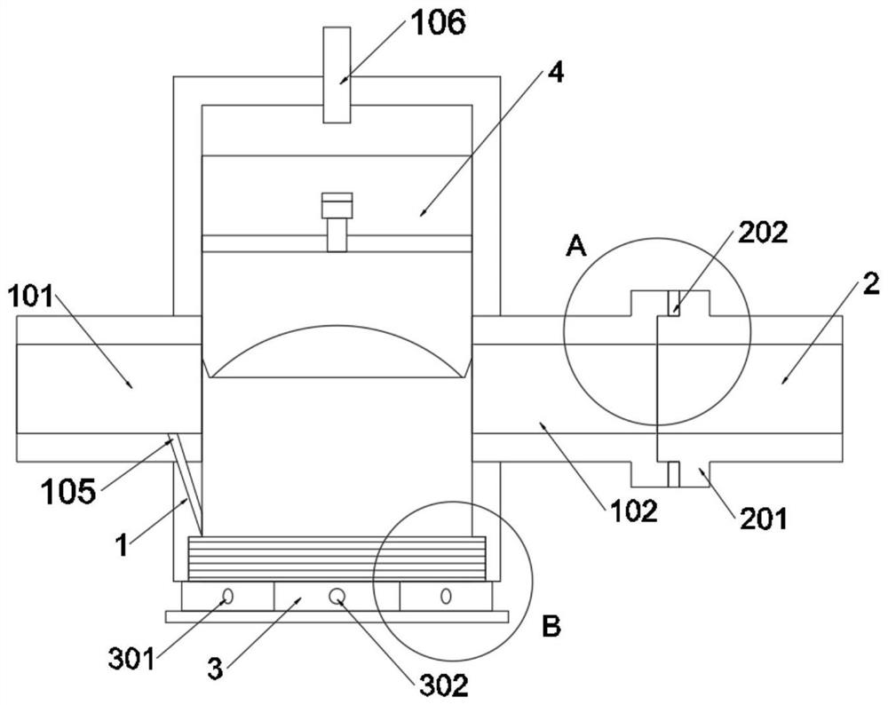
[0035] as attached figure 1 to attach Figure 8 Shown:

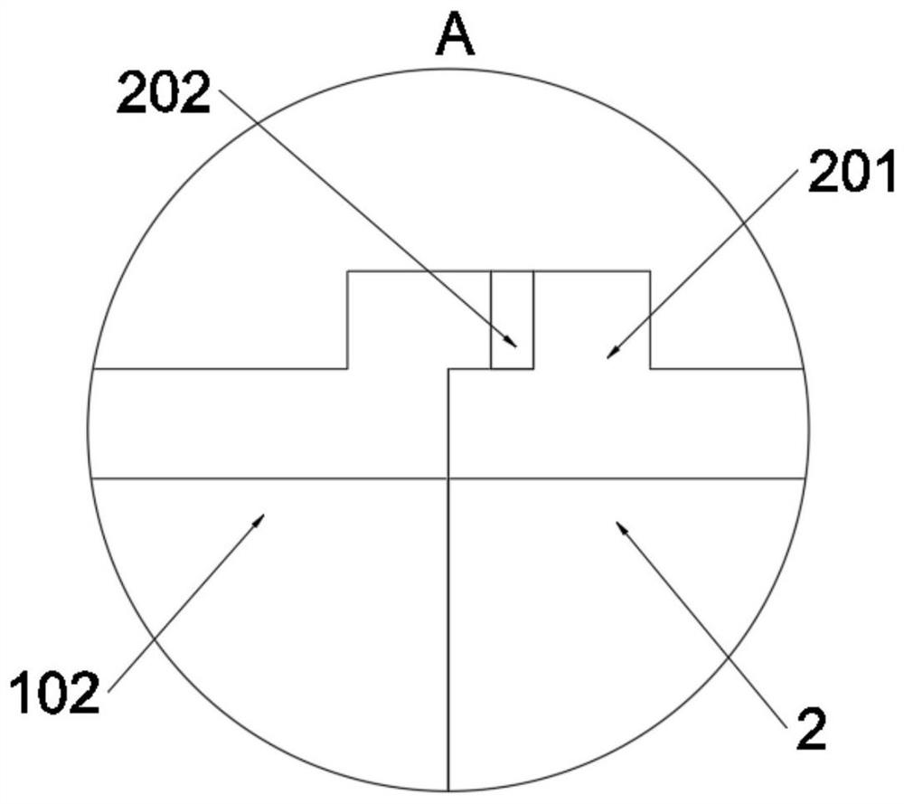
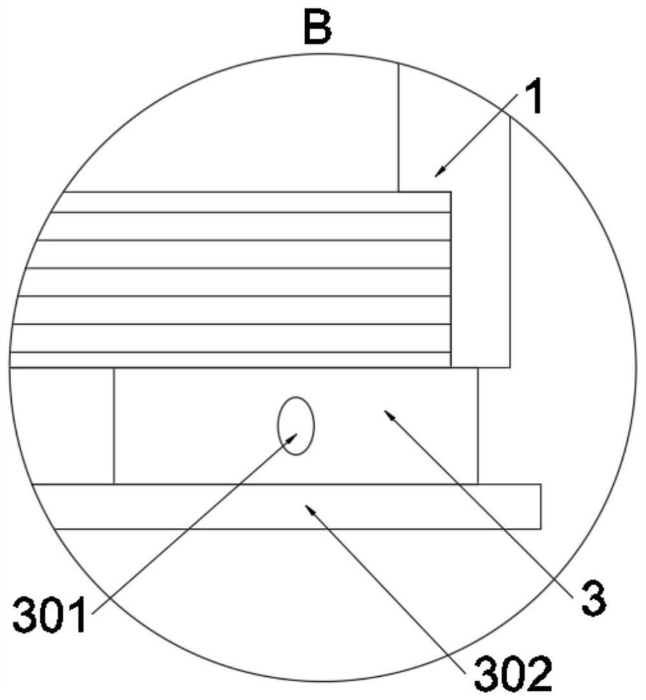
[0036]The invention provides a special valve for pneumatic conveying, which includes a valve body 1; a connecting pipe 2 is threaded on the valve body 1, and a base 3 is threaded on the valve body 1; a switch structure 4 is installed on the valve body 1, and the valve An adjustment structure 5 is welded on the main body 1; refer to Figure 4 and Figure 8 The switch structure 4 includes a sliding groove 402, a piston head 403, a sliding rod 404 and an elastic member B405. The sliding groove 402 is set at the bottom of the piston 401, and the sliding groove 402 is a stepped groove structure; the top surface of the piston head 403 is welded with a sliding rod 404, and the sliding rod 404 is a stepped shaft-shaped structure, and the sliding rod 404 is slidably connected in the sliding groove 402; the elastic part B405 is sleeved on the sliding rod 404, and the elastic part B405 is a ring structure; the outer diameter of ...


PUM


Abstract

The invention provides a valve special for pneumatic conveying and relates to the technical field of special valves. The problems that the sealing performance of a piston and a valve main body cannot be improved under the action of airflow through structural improvement, the air leakage and contact with the hand of an operator cannot be avoided through structural improvement, and automatic locking of an adjusting screw cannot be achieved at the same time through the avoiding structure are solved. The valve special for pneumatic conveying comprises a valve body. The valve body is in threaded connection with a connecting pipe, and the valve body is further in threaded connection with a base. A sliding rod is welded to the top end face of a piston head, the sliding rod is of a stepped shaft structure, and the sliding rod is connected into the sliding groove in a sliding manner. The sliding rod is sleeved with an elastic piece B, and the elastic piece B is of an annular structure. The outer diameter of the elastic piece B is equal to the outer diameter of the piston head, and the elastic piece B forms an auxiliary sealing structure of the piston, so that compression of the elastic piece B can be achieved under the resistance effect of air pressure, and then auxiliary sealing is achieved.

Description

technical field [0001] The invention belongs to the technical field of special valves, and more specifically relates to a special valve for pneumatic conveying. Background technique [0002] Fly ash transportation in coal-fired power plants belongs to the category of gas-solid two-phase flow. The movement of gas and solid particles in the conveying pipe involves various conditions such as the distribution of airflow velocity and the friction between solid particles and the pipe wall. The situation is complicated and wears heavily on the parts of the conveying system. The valve is a key component of the pneumatic conveying system, so the performance of the valve has a major impact and decisive effect on the conveying efficiency of the pneumatic conveying system and its normal operation. The valve problem is one of the main reasons for the existing problems in the existing pneumatic conveying system. . [0003] For example, the application number: CN201810504952.5, a dischar...

Claims


Application Information

Patent Timeline
Patent Type & Authority Applications(China)
IPC IPC(8): B65G53/46
CPCB65G53/46B65G2201/04
Inventor 张寿根叶一舟肖翰萧亚兵
Owner ZHEJIANG GUTE PNEUMATIC MACHINERY
Learn More