
Self-operated side valve with power failure protection function and its application method

A power-off protection and self-operated technology, which is applied in the field of self-operated side valves, can solve the problems of hydraulic or electric actuators with large volume, difficult operation, and occupying space in the cabin, achieving good stability and operability, The overall structure is simple and the effect of improving safety

Active Publication Date: 2022-04-26
CHINA SHIP SCIENTIFIC RESEARCH CENTER (THE 702 INSTITUTE OF CHINA SHIPBUILDING INDUSTRY CORPORATION)
View PDF0 Cites 0 Cited by
  • Summary
  • Abstract
  • Description
  • Claims
  • Application Information

AI Technical Summary

Problems solved by technology

[0006] 1) The existing side valves are generally driven by manual, hydraulic or electric operation. Due to the high pressure of seawater, if purely manual operation is used, the requirements for operators are high, and in the event of damage to the seawater pipeline in the cabin, the valve The surrounding may be in a state of water and fog, the environment is harsh, and the operation is difficult;
[0007] 2) The side valve adopts hydraulic or electric. In order to overcome the high pressure of seawater on the actuator, it is necessary to ensure the stability and reliability of the power source. It is necessary to install hydraulic pipelines, cables and other equipment, and the volume of the hydraulic or electric actuator is relatively large. Occupy the space in the cabin and increase the complexity of the system;
[0008] 3) In the event of a water ingress accident in the cabin, additional accidents such as power loss such as electricity and hydraulic pressure may often occur. Once the power source is lost, the hydraulic or electric side valve will not be able to close, resulting in serious accidents

Method used

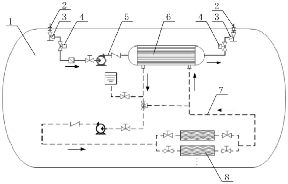

Image

  • Self-operated side valve with power failure protection function and its application method
  • Self-operated side valve with power failure protection function and its application method
  • Self-operated side valve with power failure protection function and its application method

Examples


Embodiment Construction

[0035] The specific implementation manner of the present invention will be described below in conjunction with the accompanying drawings.

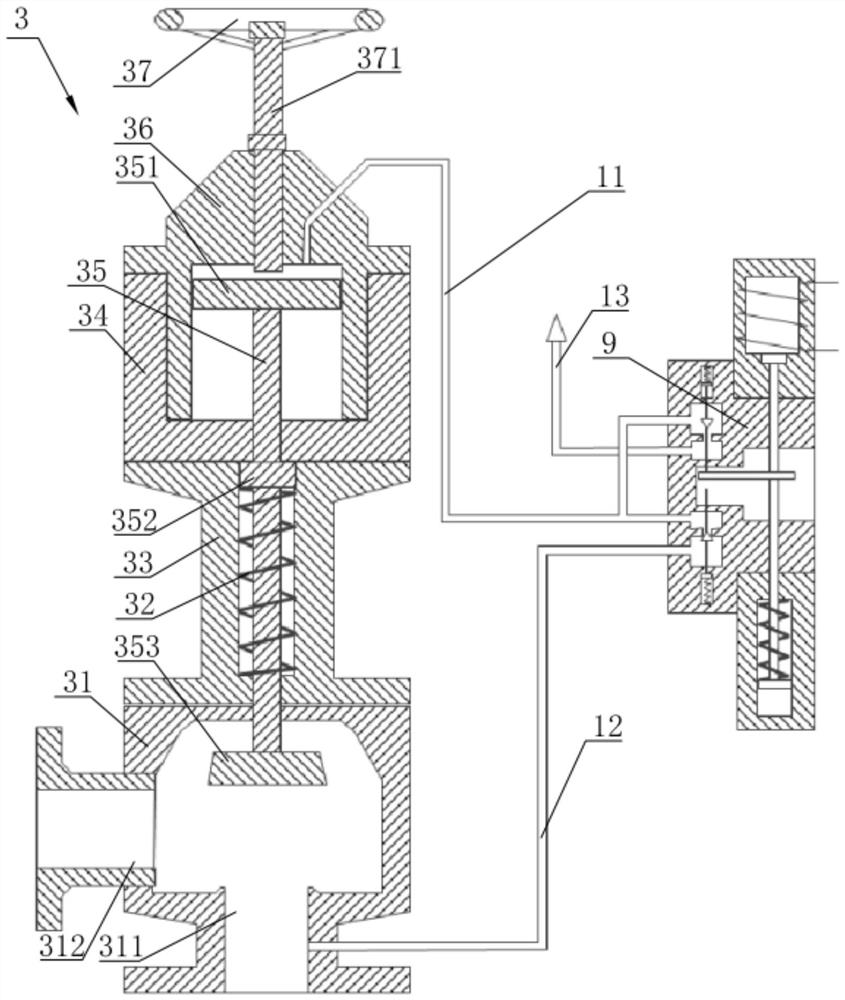
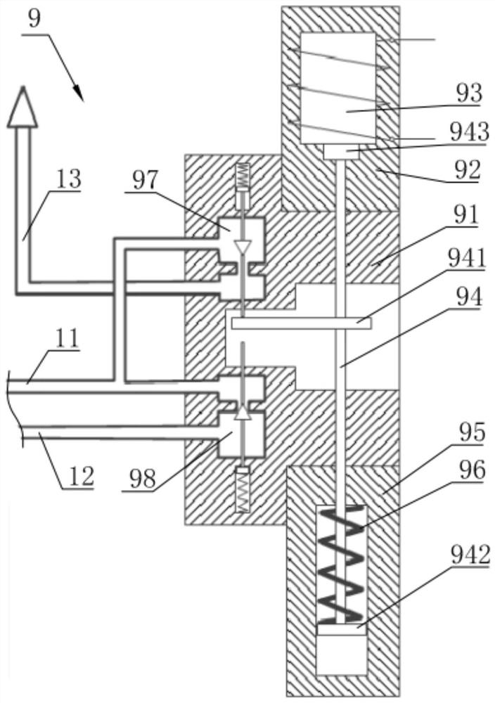
[0036] Such as figure 2 As shown, the self-operated side valve with power-off protection function in this embodiment includes a lower valve seat 31, which is provided with a flow port 1 311 and a flow port 2 312, and a top valve seat 31 is installed above the lower valve seat 31. The upper valve seat 34 of the opening, passes down from the upper valve seat 34 to the lower valve seat 31 and the main valve stem 35 is installed. The main valve stem 35 is located directly above the flow port one 311. Bonnet 36; also includes pilot valve 9, such as image 3 As shown, the pilot valve 9 includes an on-off valve 1 97 and an on-off valve 2 98 arranged at intervals opposite to each other. The opening and closing states of the on-off valve 1 97 and the on-off valve 2 98 are opposite. A push rod 941 is installed between the two off-valve valves 98,...


PUM


Abstract

The invention relates to a self-operated side valve with power-off protection function and its use method, which includes opening a lower valve seat with a flow port 1 and a flow port 2, the upper valve seat penetrates downwards to the lower valve seat to install the main valve stem, and the main valve The rod is facing the flow port 1, and the opening above the upper valve seat is equipped with a valve cover; it also includes a pilot valve, including on-off valve 1 and on-off valve 2, which are set up and down opposite to each other, and on-off valve 1 and on-off valve 2 are opened. In contrast to the closed state, a push rod is installed between the on-off valve 1 and the on-off valve 2, and the push rod pushes up the on-off valve 1 or pushes down the on-off valve 2 to realize the conversion of its open and close state; when the power is off, the push rod goes down Push the on-off valve 2 to open it, and the high-pressure seawater in the flow port 1 flows through the drainage pipe 2, the on-off valve 2, and the drainage pipe 1 to between the top of the main valve stem of the side valve and the bonnet, and pushes the main valve stem downward. As soon as the main valve stem closes the flow port from top to bottom, the side valve switches to the closed state, so that the power-off self-protection of the side valve is realized through the setting of the pilot valve.

Description

technical field [0001] The invention relates to the technical field of side valves for underwater platforms, in particular to a self-operated side valve with a power-off protection function and a method for using the same. Background technique [0002] The underwater platform can carry out tasks such as marine scientific research, marine resource exploration and exploitation, marine observation network construction, operation and maintenance underwater for a long period of time and all-weather, and will become an important equipment for deep sea exploration and development. [0003] In order to ensure that the many heating devices on the underwater platform are in good working condition, it is necessary to cool multiple types of equipment such as power systems, air-conditioning cabinets, and comprehensive purification devices for harmful gases. In order to meet the cooling water demand of the cooling system, it is necessary to introduce seawater from the outboard into the ca...

Claims


Application Information

Patent Timeline
Patent Type & Authority Patents(China)
IPC IPC(8): F16K31/40F16K31/383F16K31/08F16K1/00F16K27/02
CPCF16K31/406F16K31/383F16K31/143F16K31/0627F16K31/082F16K1/00F16K27/0254
Inventor 仝潘张万良肖友军夏彬陈康蒋竹凌
Owner CHINA SHIP SCIENTIFIC RESEARCH CENTER (THE 702 INSTITUTE OF CHINA SHIPBUILDING INDUSTRY CORPORATION)
Learn More