Floating type pipe clamp mounting device and pipe clamp mounting method
An installation device, floating technology, applied in the direction of pipes/pipe joints/fittings, pipe supports, pipe laying and maintenance, etc., can solve the problems of difficult installation of pipes and pipe clamps, and the inability of maintenance ships to enter the site, etc., to achieve low cost and cost , The effect of short construction preparation time and simple operation
- Summary
- Abstract
- Description
- Claims
- Application Information
AI Technical Summary
Problems solved by technology
Method used
Image

Examples
Embodiment 1
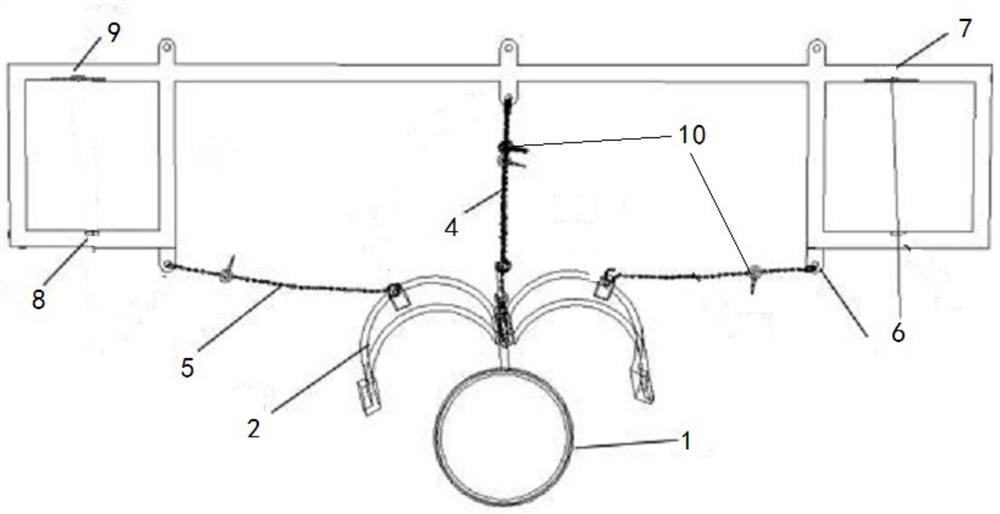
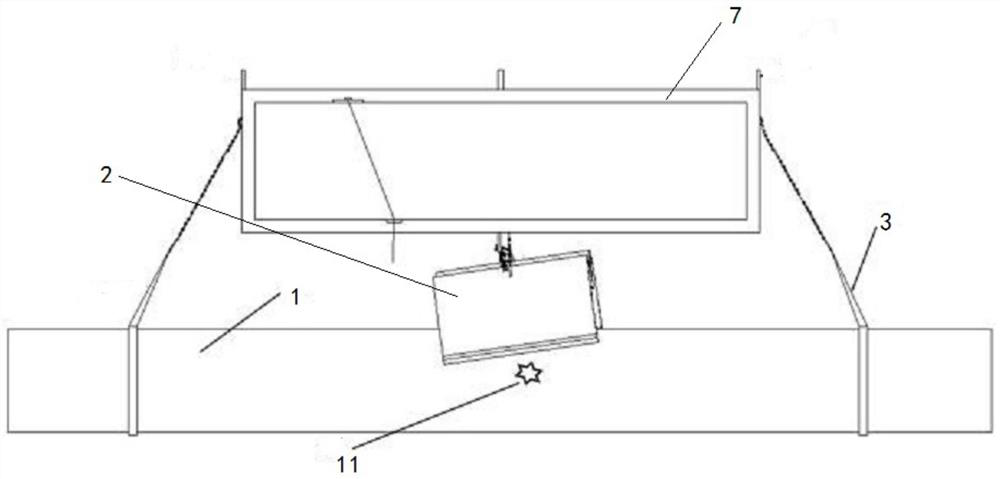
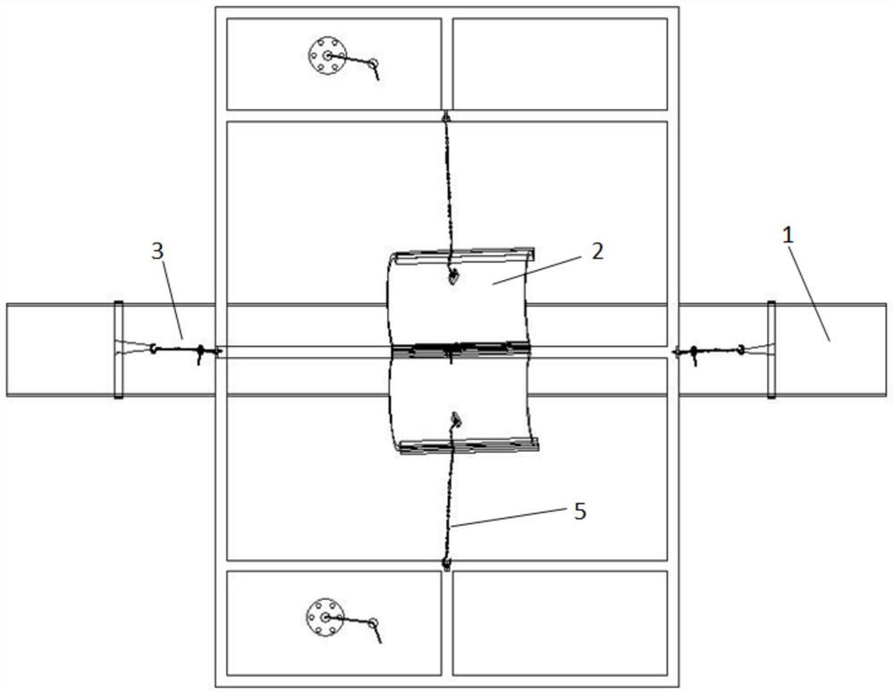
[0022] Embodiment one, such as Figure 1 to Figure 4 As shown, the invention discloses a specific implementation of each step of a floating type pipe clamp installation device as follows: the floating type pipe clamp installation device includes a bracket 7, two ends of the bracket 7 are provided with buoyant tanks 6, and between the two buoyant tanks 6 is a tube In the clamp installation work area, the bracket 7 is provided with a pipe fixing rope 3, a pipe clamp adjustment rope 5, and a pipe clamp lifting rope 4 at the pipe clamp installation work area, and each rope is respectively equipped with a hand hoist to adjust the elongation of the rope length.
[0023] Specifically, the support 7 is a steel frame structure, which is welded by two main girders and a number of support beams. The two ends of the support 7 are provided with sub-frames, and the buoyancy tank 6 is installed in the sub-frames. When the water depth of the installation point was greater than 1.5 meters, th...
Embodiment 2
[0029] Embodiment 2, the present invention also discloses a method for installing pipe clamps on damaged pipelines, which is accomplished through the following steps: (1) select the buoyant tank 6 according to the size and weight of the pipeline 1, and make the bracket 7; (2) according to the installation point Determine the size of the pipe fixing rope 3 and the lever block 10 according to the water depth and the size of the pipe clamp installation work area; (3) Make a suitable lifting point according to the weight of the pipe clamp and the predicted traction angle position; (4) According to the installation point The water depth determines the position of the buoyant tank 6; (5) Select the appropriate pipe clamp hoisting rope 4 according to the size and weight of the pipe clamp, adjust the size of the rope 5 and the lever block 10 for the pipe clamp; The card adjustment rope 5 and the pipe fixing rope 3 are respectively assembled with the hand hoist and installed on the lift...
PUM
 Abstract
Description
Claims
Application Information