
An integrated inductor

An inductor and integrated technology, applied in the field of inductance, can solve problems such as jeopardizing the normal operation of the circuit, problems with circuit power and current, etc.

Active Publication Date: 2022-03-29
深圳市方磁电子有限公司
View PDF12 Cites 0 Cited by
  • Summary
  • Abstract
  • Description
  • Claims
  • Application Information

AI Technical Summary

Problems solved by technology

[0003] When using an inductor, since the metal coil of the inductor is directly exposed and wound on the magnetic core or iron rod, because the external material will have a certain magnetic field or electric field, the metal coil is easily affected by the external magnetic and electric fields. Influenced by it, it will lead to power and current problems in the circuit, which will endanger the normal operation of the circuit.

Method used


Image

  • An integrated inductor
  • An integrated inductor
  • An integrated inductor

Examples


Embodiment 1

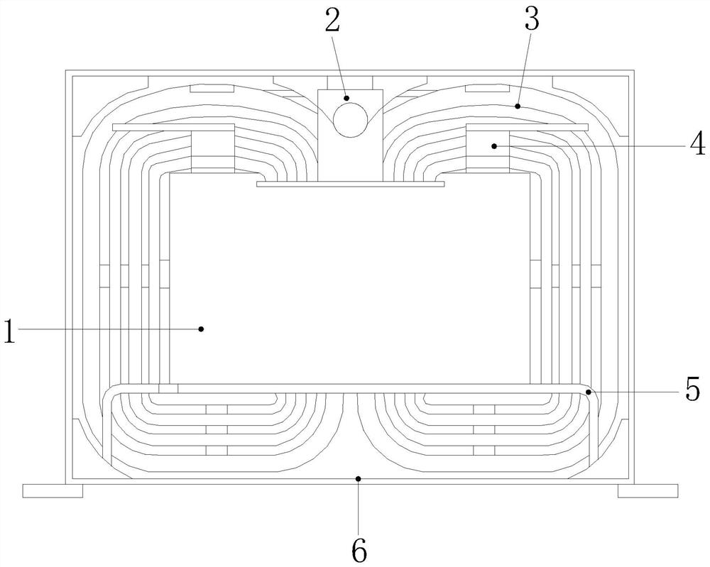
[0030] see figure 1 , the present invention provides a technical solution: an integrally formed inductor, the structure of which includes an iron core 1, a mounting part 2, a coil 3, an overlapping copper bar 4, an air channel 5, and a blocking device 6. The iron core 1 Located in the middle position inside the blocking device 6, the iron core 1 is connected to the coil 3, and both sides of the top of the iron core 1 are provided with overlapping copper bars 4 connected thereto, and the overlapping copper The row 4 is connected to the coil 3 through the iron core 1, and the end of the iron core 1 far away from the overlapping copper row 4 is connected to the air passage 5, and a mounting part 2 is provided between the iron core 1 and the blocking device 6, The mounting part 2 is fixed on the blocking device 6 .

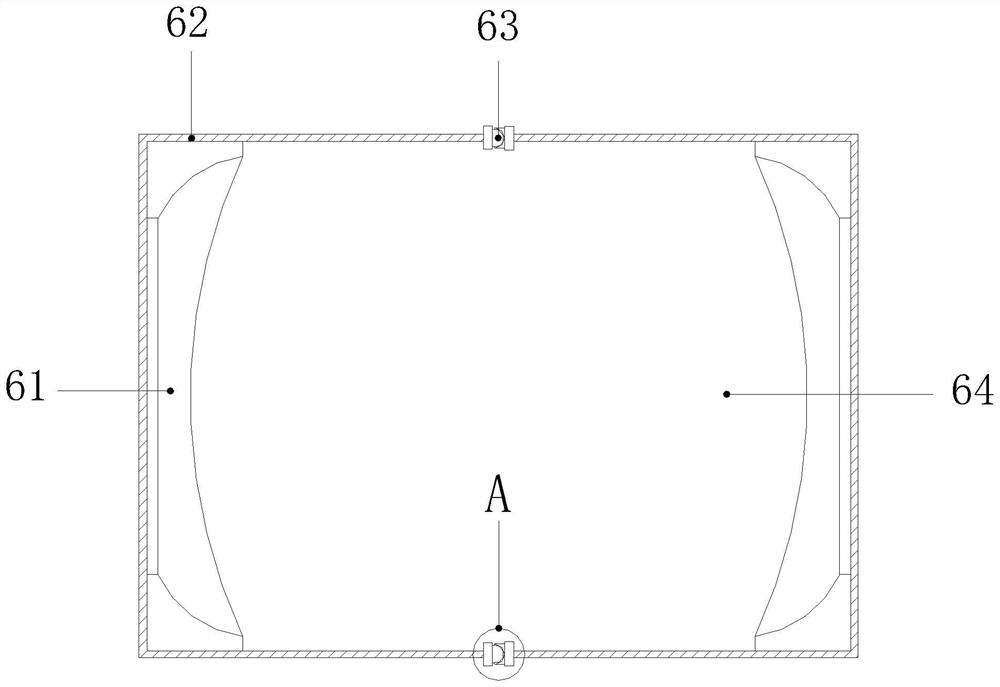
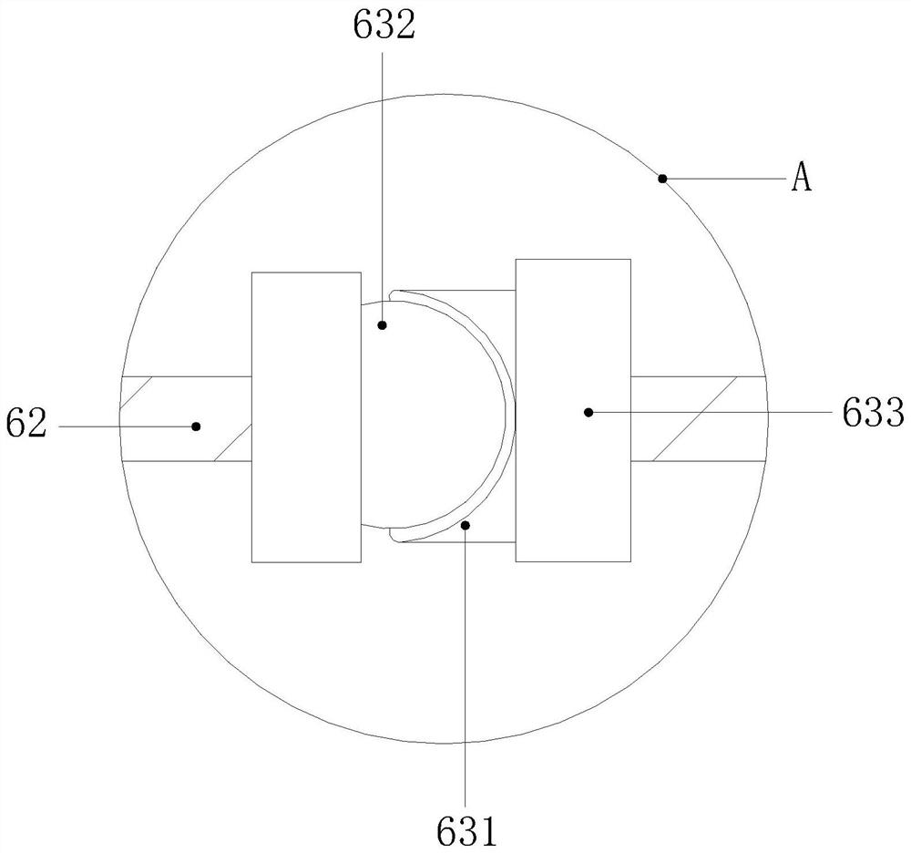
[0031] see figure 2 The blocking device 6 includes a blocking assembly 61, a protective shell 62, a movable buckle 63, and an installation cavity 64. There are tw...

Embodiment 2

[0043] see figure 1 , the present invention provides a technical solution: an integrally formed inductor, the structure of which includes an iron core 1, a mounting part 2, a coil 3, an overlapping copper bar 4, an air channel 5, and a blocking device 6. The iron core 1 Located in the middle position inside the blocking device 6, the iron core 1 is connected to the coil 3, and both sides of the top of the iron core 1 are provided with overlapping copper bars 4 connected thereto, and the overlapping copper The row 4 is connected to the coil 3 through the iron core 1, and the end of the iron core 1 far away from the overlapping copper row 4 is connected to the air passage 5, and a mounting part 2 is provided between the iron core 1 and the blocking device 6, The mounting part 2 is fixed on the blocking device 6 .

[0044] see figure 2 The blocking device 6 includes a blocking assembly 61, a protective shell 62, a movable buckle 63, and an installation cavity 64. There are tw...


PUM


Abstract

The invention discloses an integrally formed inductor, the structure of which includes an iron core, a mounting piece, a coil, an overlapping copper bar, an air channel, and a blocking device. The two ends are supported and ejected to effectively reduce the distance between the coil and the insulating layer. After the opening and closing plates on both sides of the cavity are retracted inward, a certain mutual repulsion force will be generated against each other, and the force will be transmitted outward to the sheet. , so that the sleeve can effectively support and eject the insulating layer, so that the insulating layer can effectively block the external magnetic field, prevent the influence of the magnetic and electric fields of the outer wall from interfering with the coil, and ensure the stability of the power and current in the circuit.

Description

technical field [0001] The invention relates to the field of inductance, in particular to an integrally formed inductor. Background technique [0002] Inductors are also known as chokes, reactors, and dynamic reactors. Inductors have a certain inductance, which only prevents changes in current. The role of inductors is mainly to pass DC and block AC. It mainly plays a role in filtering and oscillation in the circuit. , delay, notch, etc., through the blocking element to assist the operation of the inductor, when using the inductor, the areas that need to be improved: [0003] When using an inductor, since the metal coil of the inductor is directly exposed and wound on the magnetic core or iron rod, because the external material will have a certain magnetic field or electric field, the metal coil is easily affected by the external magnetic and electric fields. Influenced by it, it will lead to problems of power and current in the circuit, which will endanger the normal opera...

Claims


Application Information

Patent Timeline
Patent Type & Authority Patents(China)
IPC IPC(8): H01F27/02H01F27/29
CPCH01F27/022H01F27/29
Inventor 许灿河
Owner 深圳市方磁电子有限公司
Learn More