
Combined capacitor

A capacitor and combined technology, which is applied in the field of capacitance, can solve the problems of deviation feeding, accidental collision of capacitor core, and low accuracy of tin feeding position of the bracket, so as to achieve the effect of strengthening the connection relationship and ensuring the accuracy

Inactive Publication Date: 2021-06-18
李岁敏
View PDF0 Cites 0 Cited by
  • Summary
  • Abstract
  • Description
  • Claims
  • Application Information

AI Technical Summary

Problems solved by technology

[0003] Since each capacitor core is connected with the circuit board through the solder interval through the bracket, during the melting process, the capacitor core bracket will rub against the circuit board and shake back and forth in the opposite direction with the impact of the solder bar, so that the The accuracy of the tin feeding position of the bracket is not high, and deviation may occur, which will cause accidental collision between capacitor cores and shorten the service life of parallel capacitors

Method used


Image

  • Combined capacitor
  • Combined capacitor
  • Combined capacitor

Examples


Embodiment 1

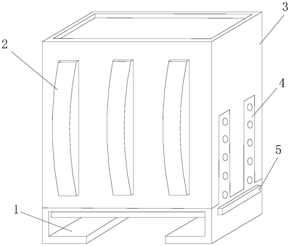
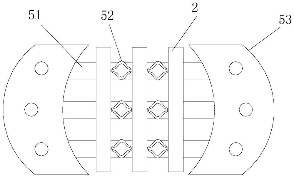
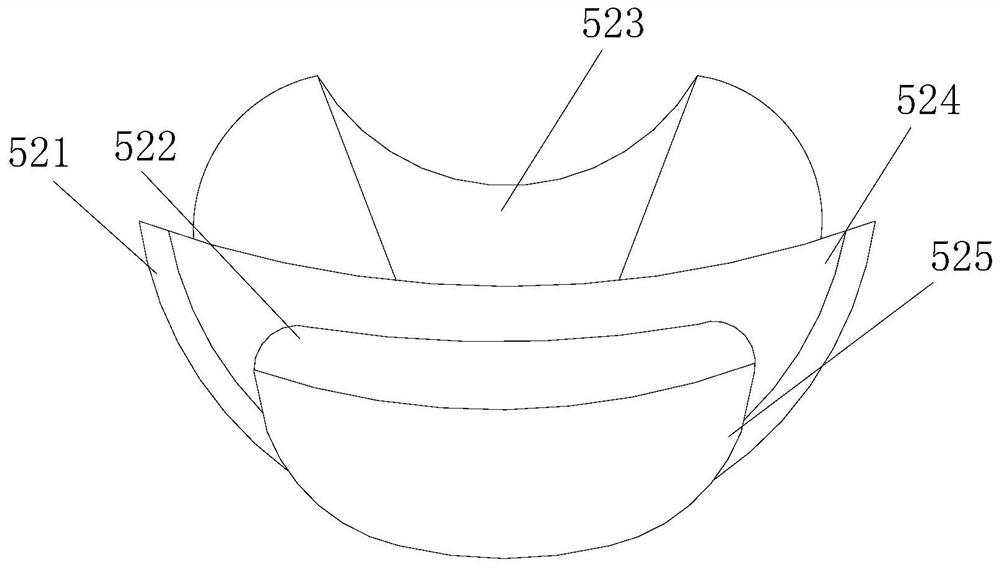
[0029] Such as Figure 1-Figure 4 As shown, the present invention provides a combined capacitor, the structure of which includes a base 1, a capacitor core 2, a main body 3, an exhaust net 4, and a receiving seat 5. The base 1 is fixedly connected to the bottom of the main body 3, and the main body 3 One side is embedded and connected with an exhaust net 4, and the inside of the main body 3 is equipped with a capacitor core 2 and a receiving seat 5. The receiving seat 5 includes a circuit board 51, a bracket 52, and a frame buckle 53, and the frame buckles 53 are fixed. A circuit board 51 is connected, and a bracket 52 is installed between the circuit board 51 and the capacitor core 2, and the bracket 52 includes a touch frame 521, a collar plate 522, a booster assembly 523, a basin 524, and a touch package 525 , the touch frame 521 is embedded and connected to the circuit board 51 through the touch package 525, the touch package 525 is fixedly connected with the collar plate ...

Embodiment 2

[0031] Such as Figure 5-Figure 8 As shown, on the basis of Embodiment 1, the present invention combines the mutual cooperation of the following structural components. The straightening piece 234 includes a sliding block 341, an outer limit layer 342, a top file 343, an end sleeve clamp 344, and a pressing buckle 345 The sliding block 341 is in oblique sliding contact with the inner side of the partition 524, and both sides are fixedly connected with a pair of pressing buttons 345, and the bottom of the pair of pressing buttons 345 is sleeved and connected with a top file 343, and the top file 343 is movable. Closed inside the protective clip 233, and its bottom is embedded with an outer limit layer 342, the outer limit layer 342 is hingedly connected to the bottom of the basin 524, and the square part 234 includes a check and balance structure 351, a limit antenna 352, and a side wing 353 , a pendulum ball 354, a balance structure 351 is installed vertically in the middle of ...


PUM


Abstract

The invention discloses a combined capacitor which structurally comprises a base, a capacitor core body, a main body, an exhaust net and a bearing seat. The base is connected to the main body, one side of the main body is connected with the exhaust net, the capacitor core body and the bearing seat are installed in the main body, the bearing seat comprises a circuit board, a support and a support buckle, and the support buckle is connected with the circuit board. The support is installed between the circuit board and the capacitor core body, a straightening piece and a supporting structure are arranged on a power assisting assembly, the straightening piece is matched with a separating basin through the supporting structure, when the capacitor core body indirectly rubs on the circuit board and shakes in the opposite direction, the supporting structure is driven by friction to swing on the separating basin through the straightening piece to incline and deviate, a fixed point position of the supporting structure relative to the low position of the capacitor core body is elastically adjusted, and the tin feeding position precision of the support is guaranteed.

Description

technical field [0001] The invention relates to the field of capacitors, in particular to a combined capacitor. Background technique [0002] A capacitor is a device that holds charges. With the development of society, the rapid changes in electronic information technology, and the continuous replacement of mechanical and electronic products, the growth of capacitors has been driven, and more and more types of capacitors have emerged. According to the application Classified capacitors include high-frequency bypass capacitors, filter capacitors, small capacitors and combined capacitors, etc.; the existing combined capacitors will have the following disadvantages when used: [0003] Since each capacitor core is connected with the circuit board through the solder interval through the bracket, during the melting process, the capacitor core bracket will rub against the circuit board and shake back and forth in the opposite direction with the impact of the solder bar, so that the ...

Claims


Application Information

Patent Timeline
IPC IPC(8): H01G15/00H01G2/06
CPCH01G2/06H01G15/00
Inventor 林旭川
Owner 李岁敏
Learn More