New energy automobile environment-friendly battery box
A technology for new energy vehicles and battery boxes, which is applied in the direction of secondary batteries, battery pack components, and isolation of batteries from their environment. It can solve the problems of difficult shock absorption and heat dissipation of new energy battery boxes, and achieve the effect of improving heat dissipation efficiency
- Summary
- Abstract
- Description
- Claims
- Application Information
AI Technical Summary
Problems solved by technology
Method used
Image
Examples
Embodiment 1
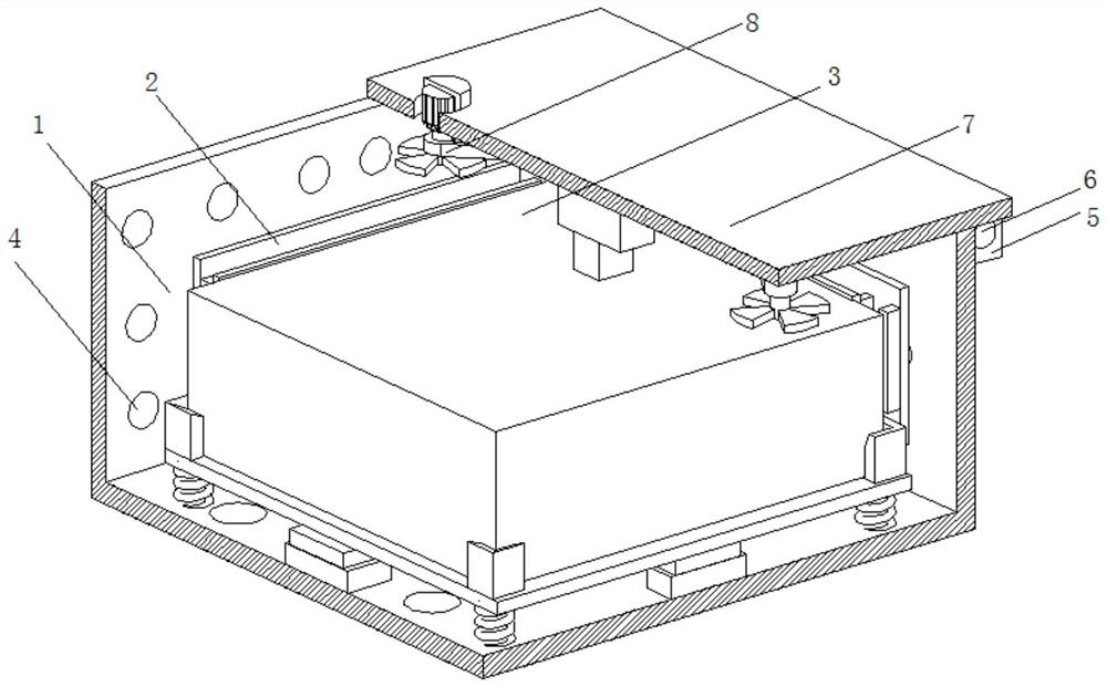
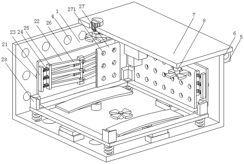
[0031] A new energy vehicle environment-friendly battery box, such as Figure 1-Figure 5 As shown, the box body 1 is included, and the inside of the box body 1 is provided with a multi-directional protection shock-absorbing mechanism 2. The surface of the multi-directional protection shock-absorption mechanism 2 is provided with a battery body 3, and the inside of the box body 1 is provided with a ventilation hole 4. The rear part of the body 1 is welded with a connecting seat 5, and the inside of the connecting seat 5 is rotatably connected with a shaft 6, and the surface of the shaft 6 is welded with a box cover 7, and the inside of the box cover 7 is provided with a heat dissipation mechanism 8, and the inner wall of the box body 1 Bonded with sound-absorbing cotton.
[0032] The heat generated and accumulated between the battery components installed in the box body 1 can be quickly dissipated by setting the vent hole 4, and the effect of reducing noise can be achieved by b...
Embodiment 2
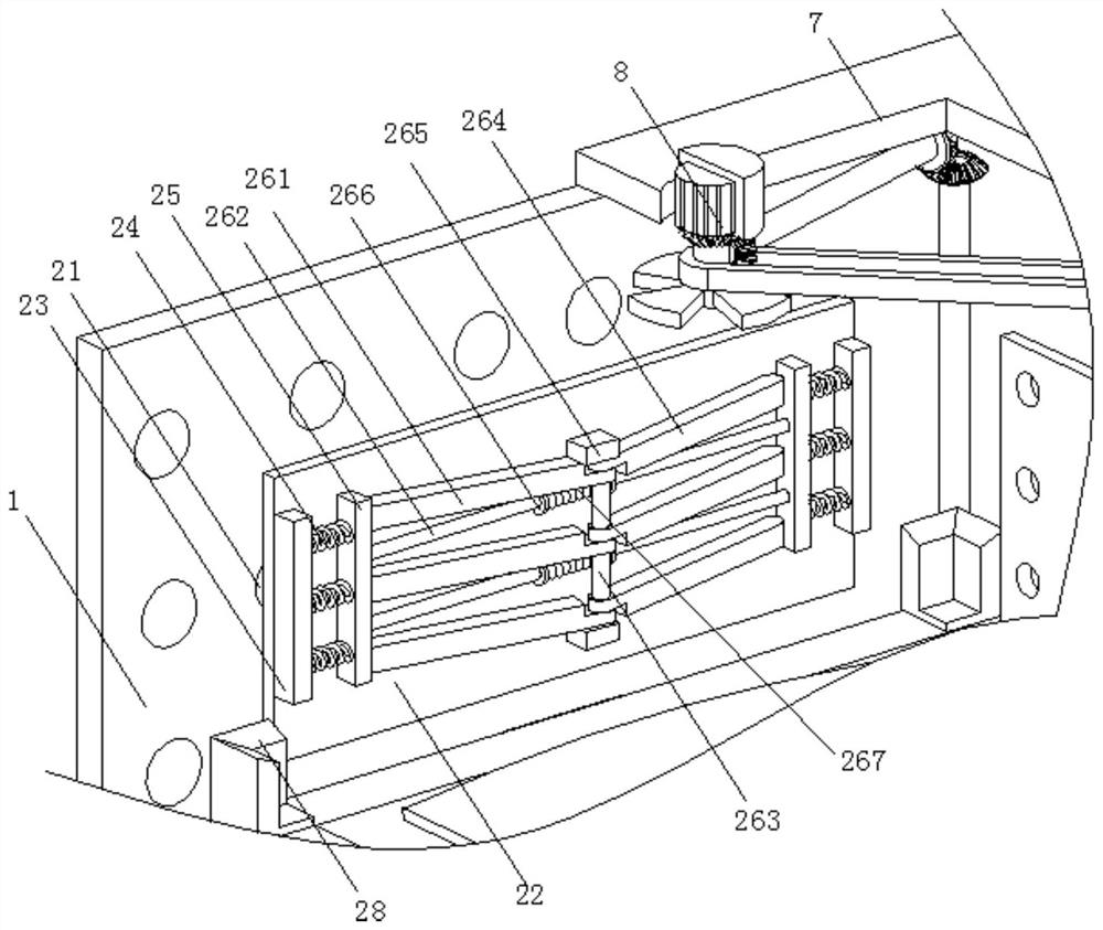
[0047] Such as Figure 6-Figure 7 As shown, on the basis of Embodiment 1, in this embodiment, the heat dissipation mechanism 8 includes a protective box 81 and a secondary roller 811, the surface of the protective box 81 is welded and fixed to the inside of the box cover 7, and the inner wall of the protective box 81 passes through The bolt is connected with a motor 82, the output shaft of the motor 82 is clamped with a main rotating roller 83, the surface of the main rotating roller 83 is welded with a bevel gear-84, the bottom end of the main rotating roller 83 is welded with a fan 85, and the surface of the bevel gear-84 is welded. Bevel gear two 86 is meshed, and the inside of bevel gear two 86 is welded with rotating rod 87, and the rear end of rotating rod 87 is welded with meshing bevel gear 88, and the surface meshing of meshing bevel gear 88 has passive bevel gear 89, and the passive bevel gear 89 A long rod 810 is welded inside.
[0048] By setting the heat dissipat...
PUM
 Abstract
Description
Claims
Application Information
 - R&D
- Intellectual Property
- Life Sciences
- Materials
- Tech Scout
- Unparalleled Data Quality
- Higher Quality Content
- 60% Fewer Hallucinations
Browse by: Latest US Patents, China's latest patents, Technical Efficacy Thesaurus, Application Domain, Technology Topic, Popular Technical Reports.
© 2025 PatSnap. All rights reserved.Legal|Privacy policy|Modern Slavery Act Transparency Statement|Sitemap|About US| Contact US: help@patsnap.com


