Energy-saving device of communication switch

A technology of energy-saving devices and switches, applied in the direction of selection devices, electrical components, etc., can solve the problems of dust easily entering the heat dissipation holes of communication machines, insufficient energy saving of fans, and increased costs, so as to avoid the difficulty of dissipating temperature, avoid dragging and detachment, and save energy. The effect of energy use

Pending Publication Date: 2021-06-18
程娟
View PDF5 Cites 0 Cited by
  • Summary
  • Abstract
  • Description
  • Claims
  • Application Information

AI Technical Summary

Problems solved by technology

[0004] The purpose of the present invention is to solve the problem that the internal structure of the communication switch in the prior art is piled up together, and the heat dissipation holes of the communication machine itself are easy to enter dust. When the dust covers the internal electronic components, etc., the heat dissipation efficiency will be greatly improved. reduce, it may burn out the internal electronic components, and the replacement increases the cost, and the fan inside the switch is often not enough to save energy, and an energy-saving device for a communication switch is proposed

Method used


Image

  • Energy-saving device of communication switch
  • Energy-saving device of communication switch
  • Energy-saving device of communication switch

Examples


Embodiment 1

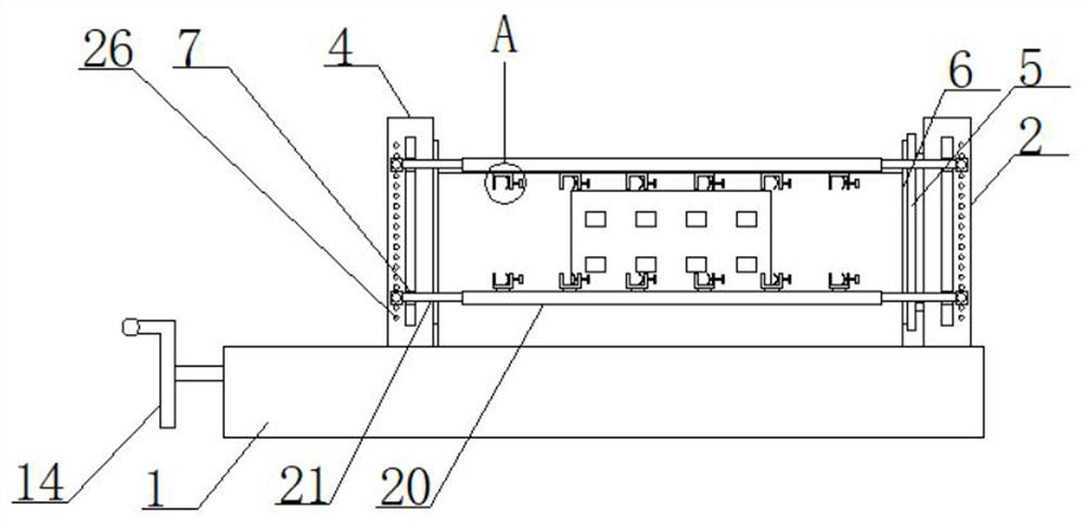
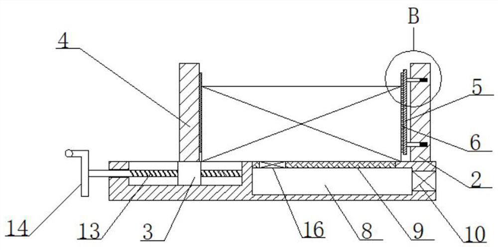
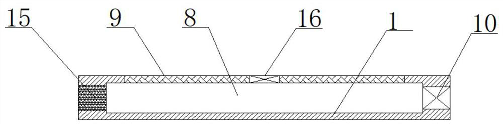
[0031] refer to Figure 1-7 , an energy-saving device for a communication switch, comprising a base 1, the top of the base 1 is fixedly connected with a fixed plate 2, and the top of the base 1 is provided with a first chute, and a first slider 3 is slidably installed in the first chute, The top of the first slider 3 is fixedly connected with a moving plate 4, and one side of the fixed plate 2 is slidably equipped with a buffer plate 5, and one side of the buffer plate 5 and the moving plate 4 is fixedly connected with a rubber pad 6, and the moving plate 4 is connected with the fixed plate. One side of the plate 2 is provided with a second chute, and two second sliders 7 are slidably installed in the two second chutes, and the four second sliders 7 are fixedly connected with telescopic mechanisms in pairs. , the two telescopic mechanisms are provided with multiple clamping mechanisms, the base 1 is provided with a cooling cavity 8, the top of the base 1 is provided with a coo...

Embodiment 2

[0042] refer to Figure 1-7, an energy-saving device for a communication switch, comprising a base 1, the top of the base 1 is fixedly connected with a fixed plate 2 by welding, and the top of the base 1 is provided with a first chute, and a first slider is slidably installed in the first chute 3. The top of the first slider 3 is fixedly connected with the moving plate 4 by welding, and the buffer plate 5 is slidably installed on one side of the fixed plate 2, and the buffer plate 5 and the side of the moving plate 4 are both fixedly connected with a rubber pad by bonding 6. A second chute is provided on one side of the moving plate 4 and the fixed plate 2, and two second sliders 7 are slidably installed in the two second chutes, and the four second sliders 7 are in pairs Both telescopic mechanisms are fixedly connected by welding, and multiple clamping mechanisms are arranged on the two telescopic mechanisms. There is a heat dissipation chamber 8 in the base 1, a heat dissipa...


PUM


Abstract

The invention belongs to the field of communication equipment, particularly relates to an energy-saving device of a communication switch, and aims to solve the problems that internal structures of an existing communication switch are stacked together, dust easily enters heat dissipation holes of the communication switch, and when the dust covers internal electronic elements and the like, the heat dissipation efficiency is greatly reduced, internal electronic components may be burnt out, and a fan in the switch always continuously works and is not energy-saving enough. The following scheme is provided: the switch comprises a base, the top of the base is fixedly connected with a fixed plate, the top of the base is provided with a first sliding groove, and a first sliding block is slidably mounted in the first sliding groove. During use, the cooling fan can be controlled through temperature, energy is effectively saved, communication switches of different sizes can be conveniently fixed during use, network cables can be fixed, the situation that the network cables are prone to being dragged and disengaged is avoided, and meanwhile the network cables are convenient to comb.

Description

technical field [0001] The invention relates to the technical field of communication equipment, in particular to an energy-saving device for a communication switch. Background technique [0002] A switch is a network device used for electrical signal forwarding. It can provide an exclusive electrical signal path for any two network nodes connected to the switch. The most common switch is an Ethernet switch, and other common ones are telephone voice switches. , fiber optic switches, etc. [0003] Existing communication switches Most of the current communication switches have a fixed structure, and the internal structures are piled up together, and the heat dissipation holes of the communication machine itself are easy to enter dust. When the dust covers the internal electronic components, etc., it will cause its heat dissipation efficiency to decrease. If it is greatly reduced, the internal electronic components may be burned out, and the replacement will increase the cost, ...

Claims


Application Information

Patent Timeline
IPC IPC(8): H04Q1/02H04Q1/10
CPCH04Q1/035H04Q1/10
Inventor 程娟
Owner 程娟
Why Eureka
Try Eureka