Water squeezing part, water squeezing device and cleaning equipment for flat mop

A flat-panel mop and component technology, applied in the field of cleaning tools, can solve the problems of low water squeezing efficiency, unclean squeezing, backflow into the mop head, etc., and achieve the effect of compact structure, reasonable design, and improved water squeezing efficiency

Pending Publication Date: 2021-06-22
成都美派环保科技有限公司
View PDF3 Cites 0 Cited by
  • Summary
  • Abstract
  • Description
  • Claims
  • Application Information

AI Technical Summary

Problems solved by technology

[0006] The present invention solves the problem that in the existing water squeezing device, the outer surface of the squeeze wheel is a closed structure, so that a relatively closed groove will be formed above the contact position between the mop head of the flat mop and the squeeze wheel. In the process of moving down and cooperating with the squeeze wheel to squeeze water, the squeezed water will accumulate in this groove and easily flow back into the mop head during the process of gravity or relative motion, resulting in the squeeze process There are problems of low water squeezing efficiency, repeated water squeezing and unclean squeezing. A water squeezing part with compact structure and reasonable design is provided. In the process of cooperating with the mop head to squeeze water, it can avoid the A closed groove is formed between the head and the water squeezing part, and the squeezed water can be separated from the mop head through the inside of the water squeezing part, which can effectively prevent the squeezed water from flowing back to the mop head, so that Effectively improve the water squeezing efficiency, the main idea is:

Method used


Image

  • Water squeezing part, water squeezing device and cleaning equipment for flat mop
  • Water squeezing part, water squeezing device and cleaning equipment for flat mop
  • Water squeezing part, water squeezing device and cleaning equipment for flat mop

Examples


Embodiment 1

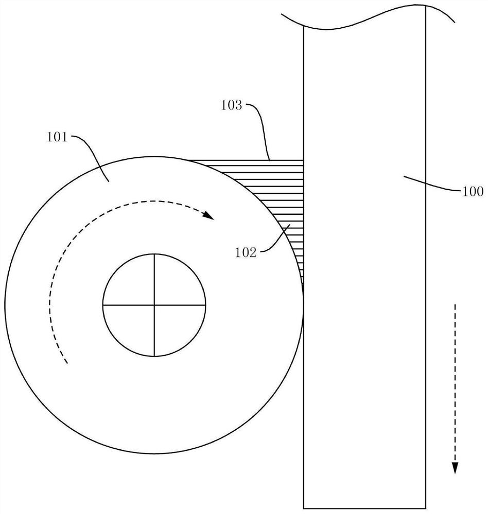
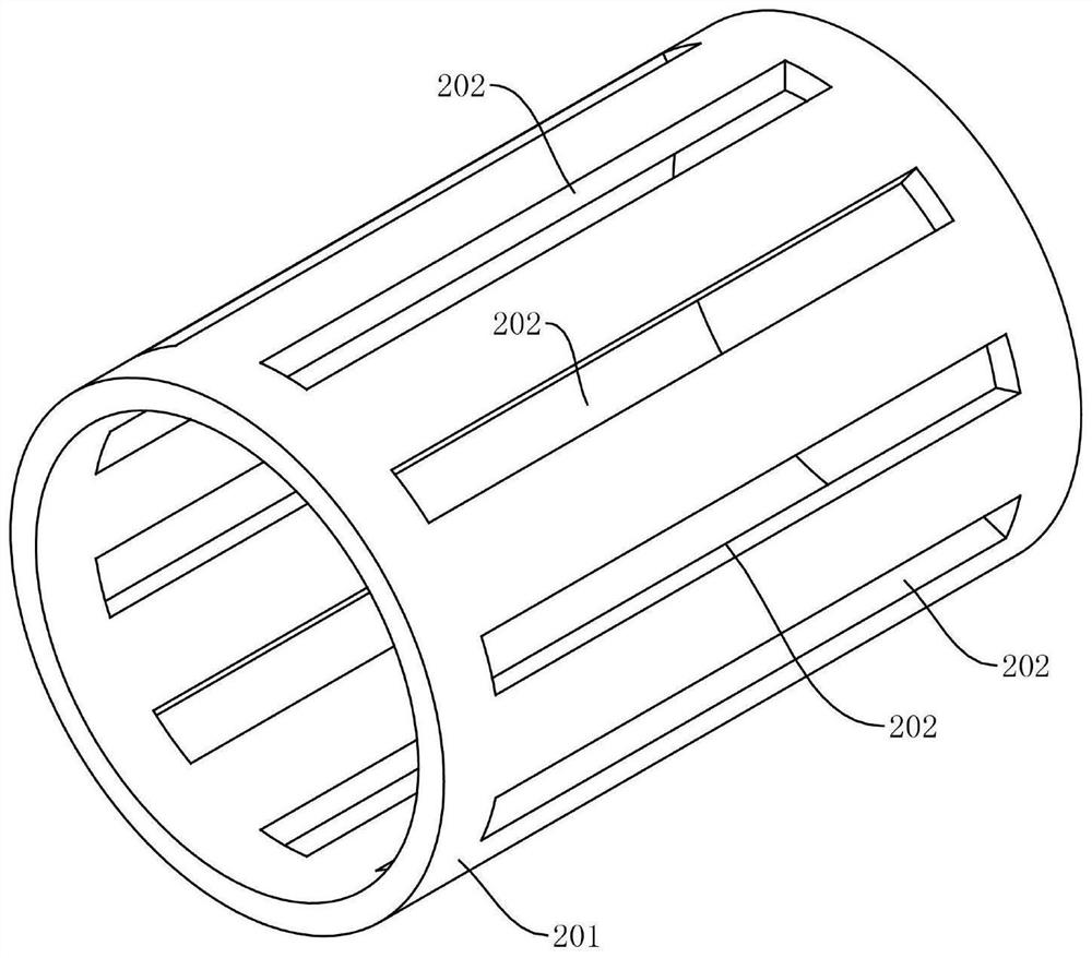
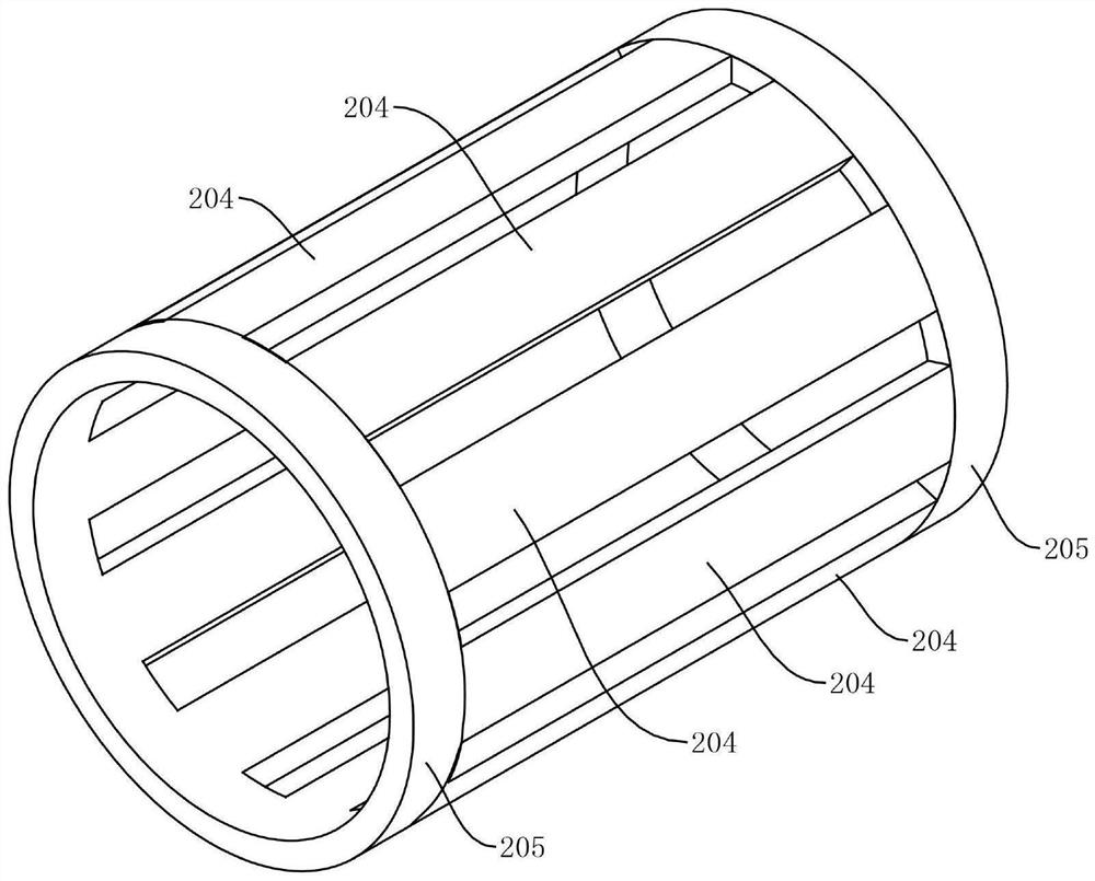
[0054] see Figure 2-Figure 6 , the present embodiment provides a water squeezing part for a flat mop, including a rotating member, and the rotating member includes a water squeezing part 201 for squeezing the mop head 100 and rotating with the movement of the mop head 100, The outer surface of the water squeezing part 201 is configured with several drainage ports 202, such as Figure 2-Figure 6 As shown, the drainage port 202 is used to follow the rotation of the water squeezing part 201, and when it is rotated between the water squeezing part 201 and the mop head 100, the drainage port 202 is used to guide the squeezed water from the drainage port 202 into the squeezing part 202. The squeezed water part 201 prevents the squeezed water from flowing back to the mop head 100, so that the squeezed water part 201 has the functions of squeezing water and guiding water at the same time.

[0055]Specifically, in this embodiment, the rotating member includes a water squeezing part 2...

Embodiment 2

[0072] In order to solve the problem of the installation of the squeeze part 201 and the drainage of internal water, the main difference between this embodiment 2 and the above-mentioned embodiment 1 is that this embodiment provides another structure of the support member 206, specifically, in this embodiment In an example, the supporting member 206 is arranged inside the rotating member, and the end of the supporting member 206 can extend out of the rotating member, such as Figure 7-Figure 9As shown, in order to install the movable support member 206, it is also possible not to extend the rotary member;

[0073] Such as Figure 7-Figure 9 As shown, in this embodiment, the drainage part includes several partitions 209 constructed between the support member 206 and the rotating member, and the partitions 209 are respectively connected to the supporting member 206 and the rotating member, and two adjacent partitions The part 209, the supporting member 206 and the rotating memb...

Embodiment 3

[0077] In order to solve the problem that the mop head 100 is easily deformed to both ends of the water squeezing part 201 during the extrusion process between the mop head 100 and the water squeezing part 201, resulting in low water squeezing efficiency, the third embodiment and the above embodiment 1 or implementation The main difference of Example 2 is that, in the water squeezing member 200 provided in this embodiment, the rotating member also includes a constraining portion 212 configured at the end of the water squeezing part 201 along the circumferential direction of the center axis of rotation of the water squeezing part 201, as Figure 10-Figure 16 As shown, the inner surface 213 of the constraining part 212 close to the squeeze part 201 can be a torus or a circular table surface, and the inner surface 213 is used to constrain and squeeze the mop head 100; specifically, in this embodiment, By constructing the restricting part 212 distributed along the circumferential d...


PUM


Abstract

The invention relates to a water squeezing part, a water squeezing device and cleaning equipment for a flat mop. The water squeezing part comprises a rotary component. The rotary component comprises a water squeezing unit used for squeezing a mop head and rotating along with the movement of the mop head, a plurality of drainage openings are formed in the outer surface of the water squeezing unit, and the drainage openings are used for rotating along with the water squeezing unit. When the rotating shaft rotates to the position between the water squeezing unit and the mop head, squeezed water is guided to flow into the water squeezing unit from the drainage openings. The water squeezing part is compact in structure and reasonable in design, in the process that the water squeezing part is matched with the mop head to squeeze water, a closed groove can be prevented from being formed between the mop head and the water squeezing part, squeezed water can be separated from the mop head through the interior of the water squeezing part, the squeezed water can be effectively prevented from flowing back to the mop head, and the water squeezing effect is improved.

Description

technical field [0001] The invention relates to the technical field of cleaning appliances, in particular to a water squeezing component, a water squeezing device and cleaning equipment for a flat mop. Background technique [0002] The mop is a commonly used cleaning tool and is widely used in daily life. At present, the commonly used mops are usually divided into two types: flat mop and rotary mop. Among them, the rotary mop is usually used in conjunction with the cleaning bucket, and the cleaning bucket can be realized by centrifugal force. Clean and dry the rotary mop, avoid hand washing; compared with the rotary mop, the flat mop has a larger cleaning area, more uniform force during use, better cleaning effect, and better application in daily life. Many; the existing flat mop usually includes a mop head and a mop bar. The mop head includes a back plate and a wiping part fixed on the back plate. The back plate is connected to one end of the mop bar. According to the mater...

Claims


Application Information

Patent Timeline
Patent Type & Authority Applications(China)
IPC IPC(8): A47L13/60
CPCA47L13/60
Inventor 谢崇万
Owner 成都美派环保科技有限公司
Why Eureka
Try Eureka