Vacuum pouring system

A vacuum pouring and vacuum technology, which is applied in the direction of casting molten material containers, safety devices, manufacturing tools, etc., can solve problems such as low work efficiency, products that cannot be poured, and product scrapping, and achieve the effect of reducing labor costs

Inactive Publication Date: 2021-06-22
ZHONGSHAN KAIXUAN VACUUM SCI & TECH CO LTD
View PDF10 Cites 0 Cited by
  • Summary
  • Abstract
  • Description
  • Claims
  • Application Information

AI Technical Summary

Problems solved by technology

[0003] Existing transformer coil products are vacuum poured manually. When replacing products, the vacuum must be broken and replaced under normal pressure. During the long pouring process, irregular personnel are required to modify according to the changing process parameters, so that To meet the stability and accuracy of the entire pouring, if the initial

Method used


Image

  • Vacuum pouring system
  • Vacuum pouring system
  • Vacuum pouring system

Examples


Embodiment Construction

[0047] Typical embodiments embodying the features and advantages of the present invention will be described in detail in the following description. It should be understood that the present invention can have various changes in different embodiments without departing from the scope of the present invention, and that the description and drawings therein are illustrative in nature and not intended to limit the present invention. invention.

[0048] In the following description of various exemplary embodiments of the invention, reference is made to the accompanying drawings, which form a part hereof, and in which are shown by way of example different exemplary structures, systems, and embodiments in which aspects of the invention may be implemented and steps. It is to be understood that other specific arrangements of components, structures, exemplary devices, systems and steps may be utilized and structural and functional modifications may be made without departing from the scope...


PUM


Abstract

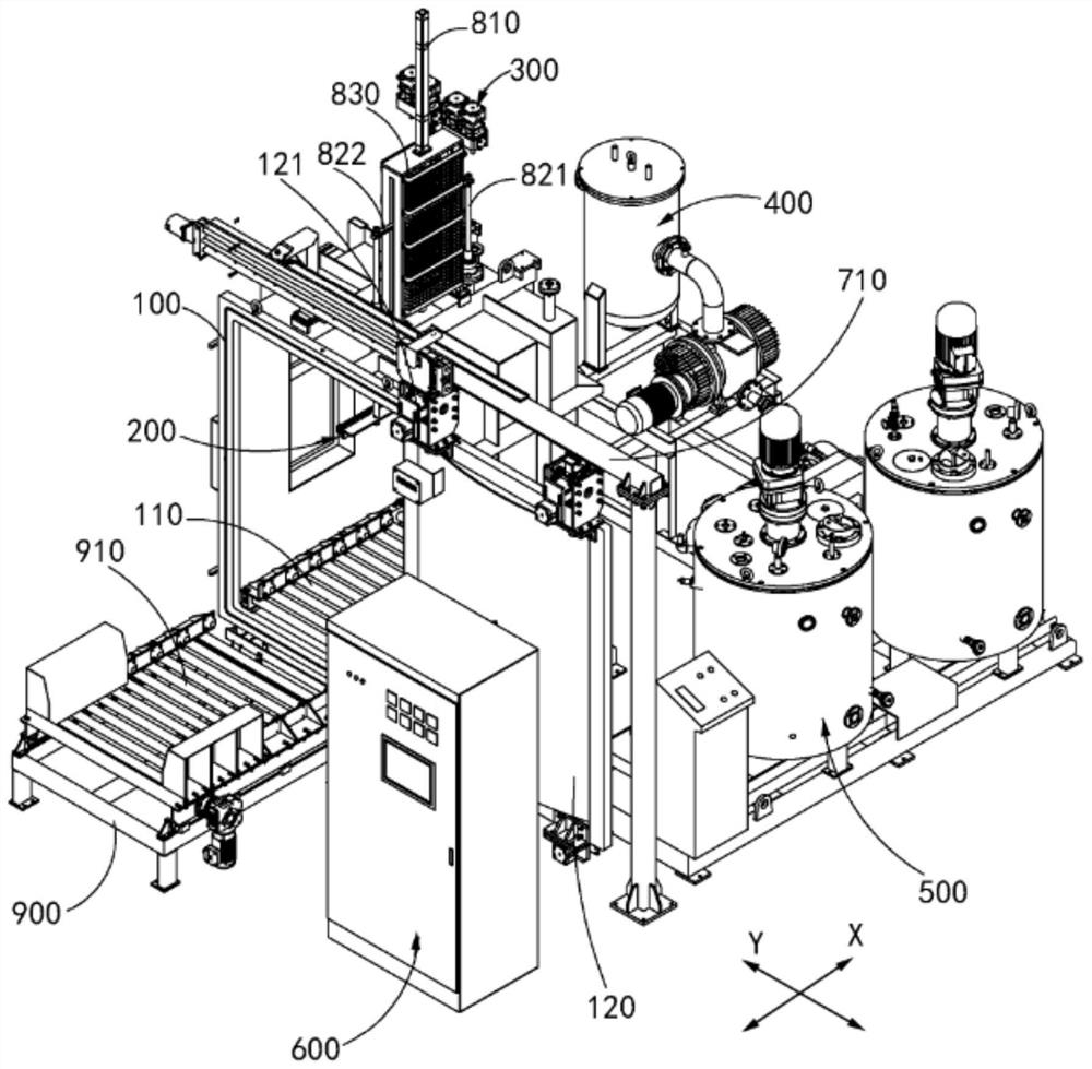
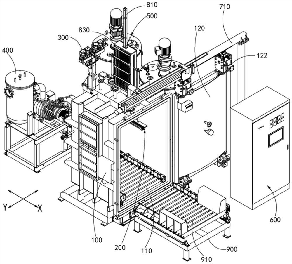
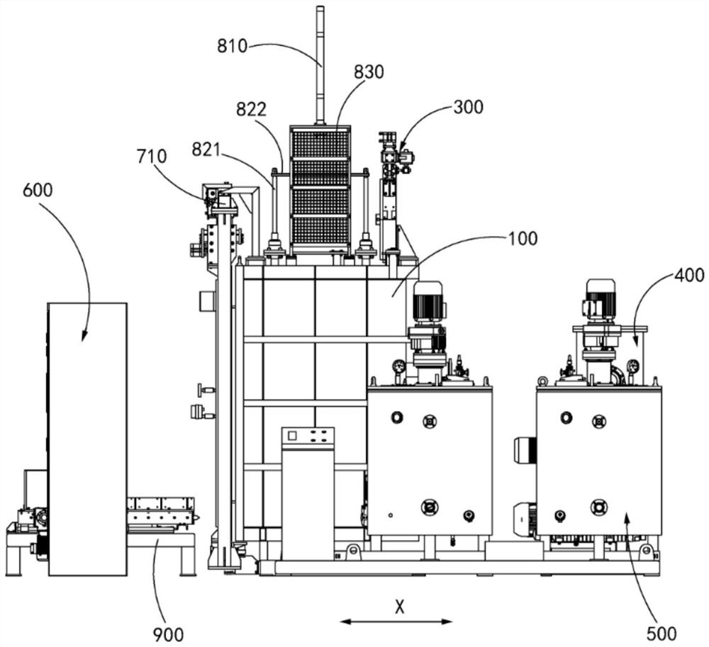
The invention provides a vacuum pouring system. The vacuum pouring system comprises a pouring tank, a pouring mechanism, a mixing mechanism, a vacuum mechanism, a degassing mechanism and a control mechanism. The pouring tank is provided with a tank cavity, a first conveying unit is arranged at the bottom of the tank cavity, and the conveying direction of the first conveying unit is the first horizontal direction. The pouring mechanism is arranged in the tank cavity in the manner of being capable of ascending and descending and being horizontally adjusted, and the horizontal adjusting direction of the pouring mechanism is the second horizontal direction perpendicular to the first horizontal direction. The mixing mechanism is connected to the pouring mechanism and used for providing pouring materials. The vacuum mechanism is connected to the tank cavity and used for vacuumizing the tank cavity. The degassing mechanism is connected to the tank cavity and is used for degassing the tank cavity. The control mechanism is connected with and controls the first conveying unit, the pouring mechanism, the mixing unit, the vacuum unit and the degassing unit.

Description

technical field [0001] The invention relates to the technical field of pouring equipment, in particular to a vacuum pouring system. Background technique [0002] With the rapid development of power demand, the construction of domestic power grids is rapidly advancing. In order to meet the rapid expansion of power equipment and power grids; the demand for transformers and their accessories in the power distribution industry is increasing, and the operation stability of power transformers , the durability puts forward higher requirements, and the transformer coil plays a vital role in the operation reliability of the transformer. [0003] Existing transformer coil products are vacuum poured manually. When replacing products, the vacuum must be broken and replaced under normal pressure. During the long pouring process, irregular personnel are required to modify according to the changing process parameters, so that To meet the stability and accuracy of the entire pouring, if th...

Claims


Application Information

Patent Timeline
IPC IPC(8): B22D18/06B22D41/12B22D46/00
CPCB22D18/06B22D41/12B22D46/00
Inventor 井峰邝光照王月侯海文林伟林罗镇江
Owner ZHONGSHAN KAIXUAN VACUUM SCI & TECH CO LTD
Why Eureka
Try Eureka