A steel pipe fixture for pipe thread processing equipment

A technology for processing equipment and pipe threads, which is applied in the direction of metal processing equipment, manufacturing tools, metal processing machinery parts, etc., can solve problems such as poor synchronization of clamping heads, unequal moving distances, and deviation of the clamping position from the specified position, etc.

Active Publication Date: 2022-05-17
杭州希纳博智能机电科技有限公司
View PDF0 Cites 0 Cited by
  • Summary
  • Abstract
  • Description
  • Claims
  • Application Information

AI Technical Summary

Problems solved by technology

[0003] The purpose of the present invention is to solve the problem that the movement of the two clamping heads is driven by two independent telescopic devices when the existing clamping device is clamping the pipe, which causes the synchronization of the two clamping heads to move. Poor performance often causes the moving distance of one clamping head to be unequal to the moving distance of the other clamping head, causing the actual clamping position to deviate from the specified position. A steel pipe clamp for pipe thread processing equipment is provided. , can effectively solve the above problems

Method used


Image

  • A steel pipe fixture for pipe thread processing equipment
  • A steel pipe fixture for pipe thread processing equipment
  • A steel pipe fixture for pipe thread processing equipment

Examples


Embodiment 1

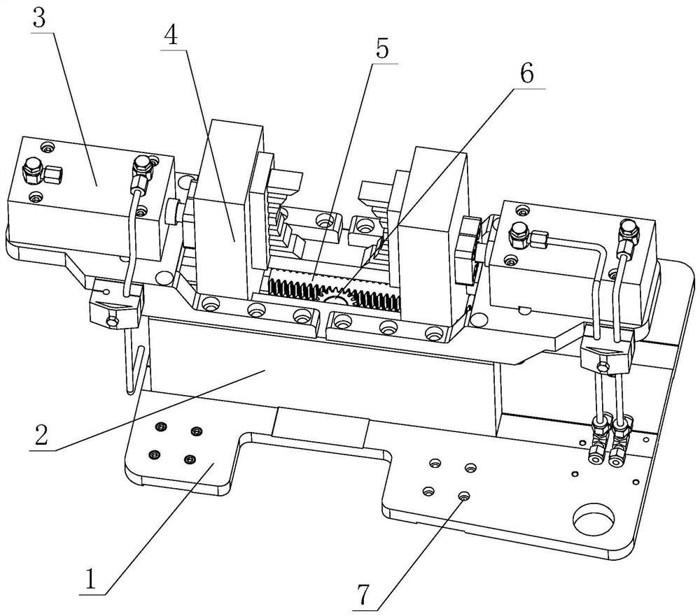
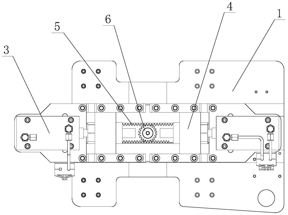
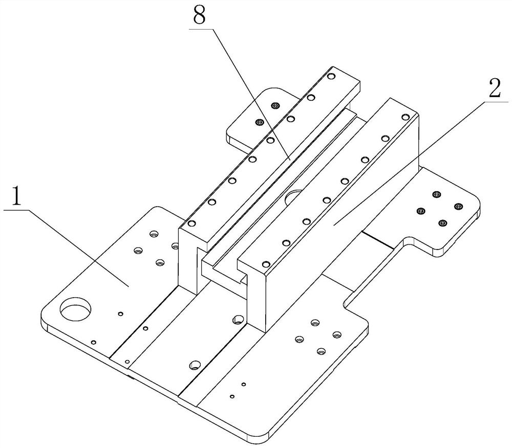
[0023] Such as Figure 1 to Figure 7 As shown, a steel pipe clamp for pipe thread processing equipment includes a bottom plate 1 on which a mounting hole 7 is arranged. The bottom plate 1 is provided with a guide platform 2 , and the guide platform 2 is provided with a guide boss 8 . Two clamping parts 4 are slidably connected to the guide table 2 , and the clamping parts 4 are provided with guide grooves 13 matching with the guide bosses 8 , and the guide bosses 8 snap into the guide grooves 13 . Both ends of the guide table 2 are respectively provided with telescopic devices 3 for driving the two clamping parts to move 4 . The moving direction of the clamping component is constrained by the cooperation of the guide groove and the guiding boss, so that the clamping component can move along the length direction of the guiding boss. A rack 5 is respectively connected to the two clamping parts 4 , and the two racks 5 are parallel to each other. A gear 6 is rotatably connected ...

Embodiment 2

[0028] The difference between embodiment 2 and embodiment 1 is that in embodiment 2, the telescopic device 3 is an air cylinder, and other structures are the same as embodiment 1.


PUM


Abstract

The invention discloses a steel pipe clamp for pipe thread processing equipment, which comprises a base plate, a guide platform is arranged on the base plate, two clamping parts are slidably connected to the guide platform, and two clamping parts for driving are respectively arranged at the two ends of the guide platform. A telescopic device for moving the clamping parts; two racks are respectively connected to a rack, and the two racks are parallel to each other, and a gear is connected to the guide table for rotation, and the two racks are respectively meshed with both sides of the gear; the bottom plate Mounting holes are provided. In the present invention, the two racks constrain the movement of the two clamping parts, realize the synchronous movement of the two clamping parts, and ensure that the moving distance of the two clamping parts is the same, thereby ensuring that the two clamping parts can clamp the pipe tight in place.

Description

technical field [0001] The invention relates to a clamp, in particular to a steel pipe clamp used in pipe thread processing equipment. Background technique [0002] When processing the pipe thread on the steel pipe, it is necessary to clamp and fix the steel pipe first, and then cut and process the surface of the steel pipe to form the pipe thread. The existing clamping device usually includes a base on which two telescopic devices are arranged. The telescopic device is usually a hydraulic cylinder. The telescopic device is connected with a head. Place the steel pipe between the two clamping heads, and then the two clamping heads clamp the steel pipe under the drive of the telescopic device. When the existing clamping device is in use, since the movement of the two clamping heads is driven by two independent telescopic devices, the synchronization of the two clamping heads is poor when moving, which often causes one of the clamping heads to be clamped. The movement distanc...

Claims


Application Information

Patent Timeline
Patent Type & Authority Patents(China)
IPC IPC(8): B23Q3/08B23G1/52
CPCB23Q3/064B23Q3/082B23G1/52Y02P70/10
Inventor 赵宗强
Owner 杭州希纳博智能机电科技有限公司
Why Eureka
Try Eureka