Convenient 3D printing equipment

A 3D printing and equipment technology, applied in the field of 3D printing, can solve the problems of not meeting the needs of use, easy to slip on the bolt, shaking of the spray gun and the mechanical arm, etc., to avoid the effect of excessive temperature

Inactive Publication Date: 2021-06-22
威海杰凯智能科技有限公司
View PDF6 Cites 0 Cited by
  • Summary
  • Abstract
  • Description
  • Claims
  • Application Information

AI Technical Summary

Problems solved by technology

[0004] Most of the existing convenient 3D printing equipment use the mechanical arm to drive the spray gun to move for printing. The mechanical arm and the spray gun are basically fixed and installed with bolts. Since the bolts are prone to slipping during the installation process, resulting in the spray gun The problem of shaking with the robotic arm does not meet the needs of use

Method used


Image

  • Convenient 3D printing equipment
  • Convenient 3D printing equipment
  • Convenient 3D printing equipment

Examples


Embodiment 1

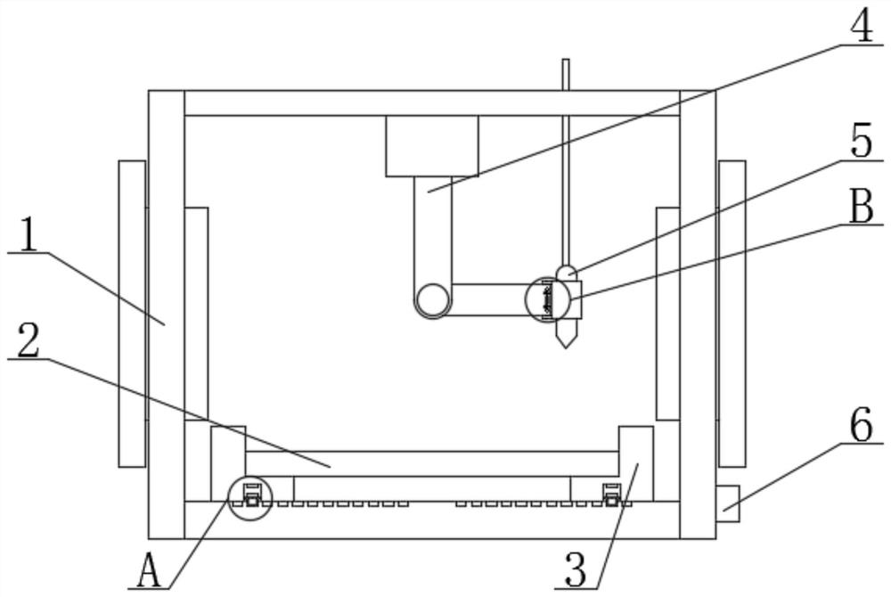
[0027] see Figure 1-5 , the present invention provides a technical solution: a convenient 3D printing device, comprising: a box body 1; Sectional structure, and the mechanical arm 4 is driven by a hydraulic device, and the hydraulic device is electrically connected to the controller; a spray gun 5, and the inside of the box 1 is fixedly installed with a spray gun 5 through a feeding pipe; a fixed sleeve 12 , the surface of the spray gun 5 is fixedly installed with a fixed sleeve 12; the fixed plate 7, the two ends of the fixed sleeve 12 and the adjacent side of the mechanical arm 4 are fixedly welded with the fixed plate 7; the installation mechanism 8, the installation mechanism 8 includes a sliding plate 81, a spring 82, a second mounting groove 83 and an insertion rod 84, the bottom side of the mechanical arm 4 is provided with a second mounting groove 83, and both ends of the second mounting groove 83 are movably inserted There is an insertion rod 84, and one end of the ...

Embodiment 2

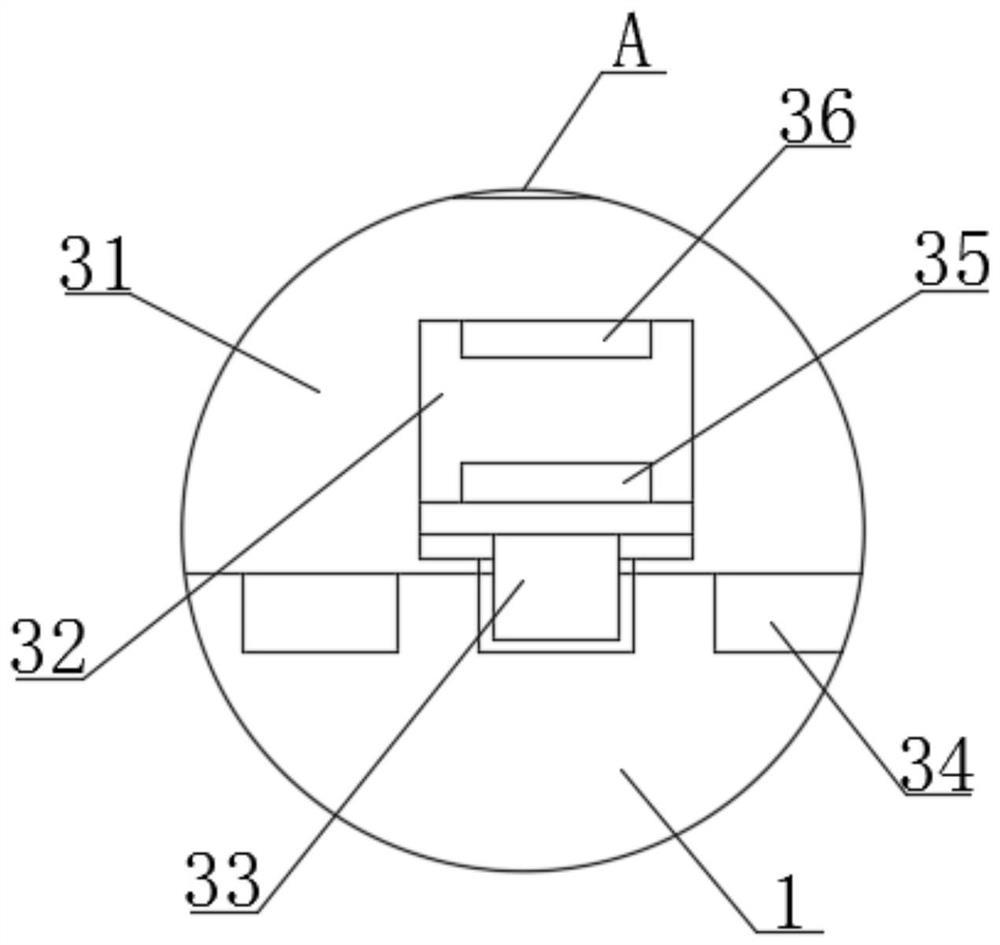
[0029] As a preferred solution of Embodiment 1, the adjustment mechanism 3 includes a limit plate 31, a first installation groove 32, a clamping column 33, an iron block 35 and an electromagnet 36, and the inner wall bottom of the box body 1 is on both sides. Slidingly connected to the limiting plate 31, the bottom of the limiting plate 31 is provided with a first installation groove 32, the bottom of the first installation groove 32 is movably inserted with a clamping column 33, and the top of the clamping column 33 is fixedly installed There is an iron block 35, an electromagnet 36 is fixedly installed on the top of the inner wall of the first installation groove 32, the electromagnet 36 is electrically connected with the controller 6, and the bottom of the clamping post 33 is engaged with the bottom of the inner wall of the box body 1. The positioning plate 2 is engaged and connected between the limiting plates 31, and the cross section of the limiting plate 31 is an L-shape...

Embodiment 3

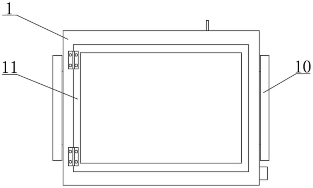
[0031]As a preferred solution of Embodiment 1, a limit mechanism 9 is fixedly installed between the sliding plates 81, the limit mechanism 9 includes a block 91 and a limit rod 92, and the slide plate 81 is located in the second installation groove One end of the outside of 83 is all engaged with a block 91, and the stop bar 92 is fixedly welded between the end of the block 91 away from the sliding plate 81, and the block 91 is engaged with the sliding plate 81, and the stop bar 92 Under the action of the sliding plate 81, it can effectively prevent the sliding plates 81 from moving towards each other, and the distance between the sliding plates 81 can be limited to avoid shaking during the printing process, and to avoid tight installation due to the contraction of the spring 82. For the problem, both sides of the box body 1 are fixedly equipped with a heat dissipation mechanism 10, the heat dissipation mechanism 10 includes a heat conduction plate and a heat dissipation plate,...


PUM


Abstract

The invention discloses convenient 3D printing equipment. The convenient 3D printing equipment comprises a box body, a mechanical arm, a spray gun, a fixed sleeve, fixed plates and a mounting mechanism.The mechanical arm is fixedly mounted at the top of the inner wall of the box body. The spray gun is fixedly mounted in the box body through a material conveying pipe. The fixed sleeve is fixedly mounted on the surface of the spray gun. The fixed plates are fixedly welded to the two ends of the side, adjacent to the mechanical arm, of the fixed sleeve. The mounting mechanism comprises a sliding plate, a spring, a second mounting groove and an insertion rod, and the second mounting groove is formed in one side of the bottom of the mechanical arm. The problems that most existing convenient 3D printing equipment adopts mechanical arms to drive spray guns to move to achieve printing, the mechanical arms and the spray guns are basically fixedly mounted through bolts, due to the fact that the bolts are prone to slipping in the mounting process, the spray guns and the mechanical arms shake, and the use requirement is not met are effectively solved.

Description

technical field [0001] The invention relates to the technical field of 3D printing, in particular to a convenient 3D printing device. Background technique [0002] 3D printing is a kind of rapid prototyping technology. It is a technology based on digital model files and using bondable materials such as powdered metal or plastic to construct objects by layer-by-layer printing. 3D printing is usually achieved using digital technology material printers. It is often used to make models in the fields of mold manufacturing and industrial design, and is gradually used in the direct manufacture of some products. There are already parts printed using this technology. The technology has applications in jewelry, footwear, industrial design, architecture, engineering and construction, automotive, aerospace, dental and medical industries, education, geographic information systems, civil engineering, firearms, and other fields. [0003] However, there are some disadvantages in the tradi...

Claims


Application Information

Patent Timeline
Patent Type & Authority Applications(China)
IPC IPC(8): B29C64/112B29C64/20B29C64/30B33Y30/00
CPCB29C64/112B29C64/20B29C64/30B33Y30/00
Inventor 宫腾飞宫文涛刘露
Owner 威海杰凯智能科技有限公司
Why Eureka
Try Eureka