
Deep well filling pipeline operation condition ultrasonic diagnosis system and method

A technology for filling pipelines and ultrasonic diagnosis, which is applied in pipeline systems, mechanical equipment, gas/liquid distribution and storage, etc. The effect of easy maintenance

Active Publication Date: 2021-06-22
NORTHEASTERN UNIV
View PDF14 Cites 0 Cited by
  • Summary
  • Abstract
  • Description
  • Claims
  • Application Information

AI Technical Summary

Problems solved by technology

However, the existence of the pressure sensor will interfere with the fluid field in the filling pipeline, and the wear resistance of the pressure sensor is high, and the impact of large-size aggregates in the slurry can easily cause the pressure sensor to fail, and there are difficulties in maintenance The problem

Method used


Image

  • Deep well filling pipeline operation condition ultrasonic diagnosis system and method
  • Deep well filling pipeline operation condition ultrasonic diagnosis system and method
  • Deep well filling pipeline operation condition ultrasonic diagnosis system and method

Examples


Embodiment Construction

[0024] The present invention will be further described in detail below in conjunction with the accompanying drawings and specific embodiments.

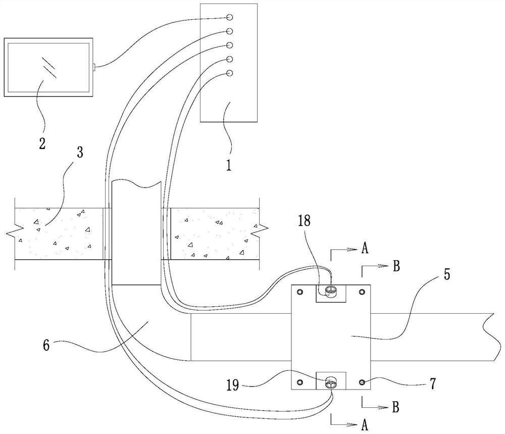
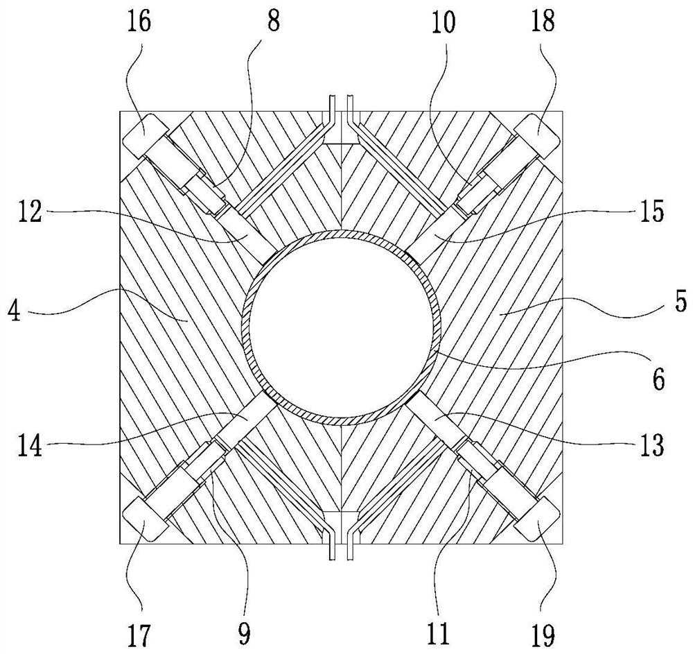
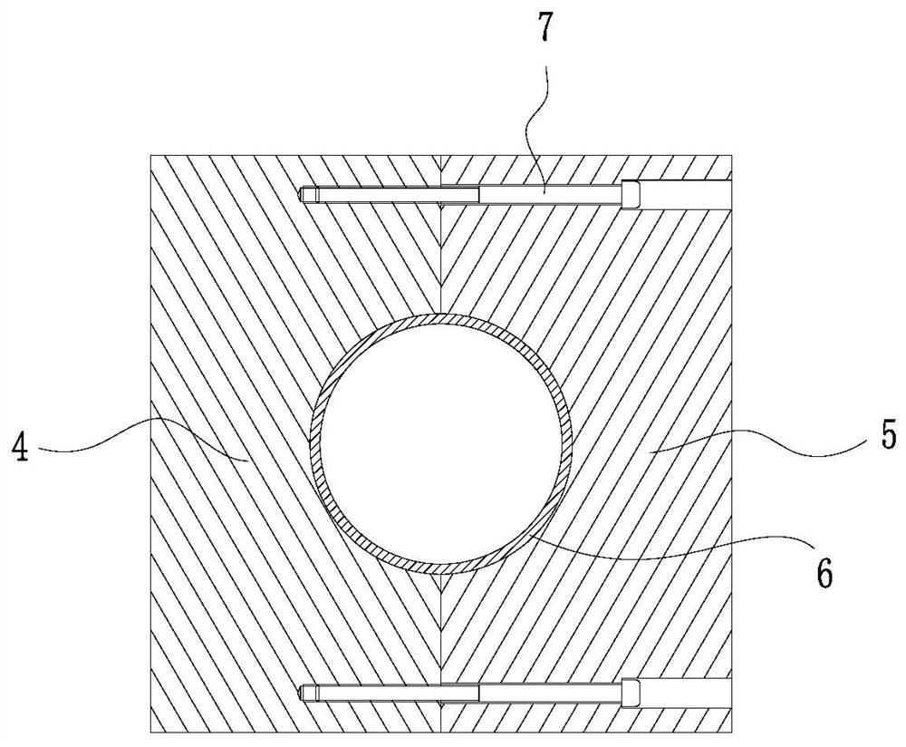
[0025] Such as Figure 1~3 As shown, an ultrasonic diagnostic system for deep well filling pipeline operating conditions includes an ultrasonic probe set, an ultrasonic probe positioning seat, a control box 1 and a display 2; the control box 1 and the display 2 are located on the ground 3, and the display 2 passes through The data line is electrically connected to the control box 1; the positioning seat of the ultrasonic probe adopts a two-half combination structure, which is divided into the left half positioning seat 4 of the ultrasonic probe and the right half positioning seat 5 of the ultrasonic probe; when the positioning seat of the ultrasonic probe is in a combined state , the center of the ultrasonic probe positioning seat is the wearing and holding hole of the filling pipeline 6, and the outer contour shape of the ultrasonic ...


PUM


Abstract

The invention discloses a deep well filling pipeline operation condition ultrasonic diagnosis system and method. The system comprises an ultrasonic probe group, an ultrasonic probe positioning seat, a control box and a display; the control box is electrically connected with the display; and the ultrasonic probe positioning seat is of a combined structure, a filling pipeline penetrating clamping hole is formed in the center, the outer contour is square, and four probe mounting holes are formed in the four corners of diagonal lines; and the ultrasonic probe group comprises P-wave and S-wave transmitting and receiving probes, and the four probes are located in the four probe mounting holes, paired in the same group and electrically connected with the control box. The method comprises the following steps of collecting P-wave and S-wave calibration data; sequentially mounting the ultrasonic probe positioning seat and the ultrasonic probe groups at filling pipeline selected monitoring points; exciting the P-wave and S-wave transmitting probes, collecting P-wave and S-wave waveform data, and repeating the operation at least three times; rotating the ultrasonic probe positioning seat by 90 degrees, and repeatedly collecting monitoring data; and comparing the monitoring data with the calibration data, and judging whether a filling pipeline is in a standard operation condition or not.

Description

technical field [0001] The invention belongs to the technical field of mine tailings filling, and in particular relates to an ultrasonic diagnosis system and method for operating conditions of deep well filling pipelines. Background technique [0002] With the depletion of mineral resources in the shallow part of the earth, mining is gradually progressing to the deep part. In order to ensure the deep underground mining process and the stability of the surrounding rock, the goaf will be filled. In addition, from the perspective of environmental protection, in order to reduce the accumulation of tailings on the ground, the filling process that makes full use of tailings materials has been favored by a large number of mining companies. Filling is to optimize the ratio of tailings, cement and water, from low to high concentration, configure it into slurry to paste, and finally transport it to the deep underground stope through pipelines. [0003] In the process of pumping or se...

Claims


Application Information

Patent Timeline
IPC IPC(8): F17D5/00F17D3/01
CPCF17D5/00F17D3/01
Inventor 石磊张希巍姜海强
Owner NORTHEASTERN UNIV
Features
  • Generate Ideas
  • Intellectual Property
  • Life Sciences
  • Materials
  • Tech Scout
  • Unparalleled Data Quality
  • Higher Quality Content
  • 60% Fewer Hallucinations
Learn More