
Dynamic and static transfer signal connection supporting device and digital signal dynamic and static transfer device

A technology for supporting device and signal connection, which is applied in the direction of two-part connecting device, parts of connecting device, flexible/rotatable wire connector, etc., which can solve the problems of time-consuming and laborious maintenance and replacement, limited installation space, and difficult operation. , to achieve the effect of increasing stability and anti-interference, easy maintenance and maintenance, and easy processing

Active Publication Date: 2021-06-22
SUZHOU SILAIKE INTELLIGENT MOLD MFG CO LTD
View PDF3 Cites 0 Cited by
  • Summary
  • Abstract
  • Description
  • Claims
  • Application Information

AI Technical Summary

Problems solved by technology

[0003] In the traditional rotary motion mechanism, the dynamic and static signals are connected through the line terminals. It is very cumbersome to repair the line or replace the line, which is time-consuming and labor-intensive.
Difficult access in the radial direction of rotation due to limited installation space
[0004] If the signal to be exported is a single signal, the circuit is simple, and the traditional line terminal connection can do it; but if the signal to be exported is many and complicated, and it is accompanied by strong current, the traditional line terminal will be very cumbersome, maintenance and replacement Time-consuming and labor-intensive, too many lines and limited space will cause interference between signals; flexible lines are often subject to certain impacts on moving mechanisms, and traditional terminal connections will affect the service life of the lines

Method used


Image

  • Dynamic and static transfer signal connection supporting device and digital signal dynamic and static transfer device
  • Dynamic and static transfer signal connection supporting device and digital signal dynamic and static transfer device
  • Dynamic and static transfer signal connection supporting device and digital signal dynamic and static transfer device

Examples


Embodiment Construction

[0034] In view of the deficiencies in the prior art, the inventor of this case was able to propose the technical solution of the present invention after long-term research and extensive practice. The technical solution, its implementation process and principle will be further explained as follows.

[0035] In order to overcome the problems in the prior art, the present invention provides a dynamic and static relay signal connection support device, which is intended to divide and regulate various complex signals in motion, optimize the distribution of motion loads, reduce the impact of the line, improve the service life of the line and Maintenance efficiency, the signal is connected with a special connector with shielding, which can reduce the mutual interference between various signals as much as possible, improve the speed of line replacement, and increase the stability and control accuracy of the motion mechanism.

[0036] An embodiment of the present invention provides a co...


PUM


Abstract

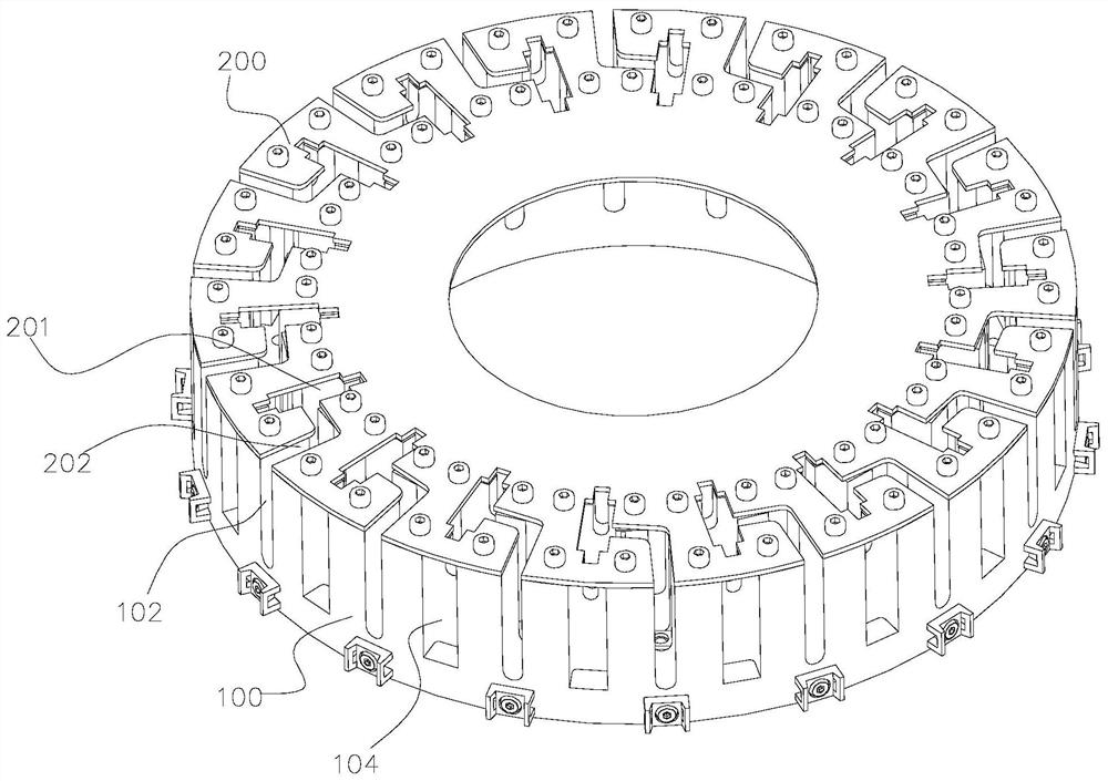
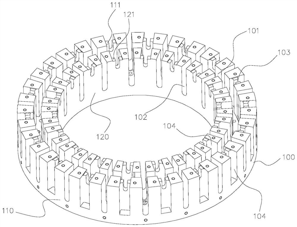
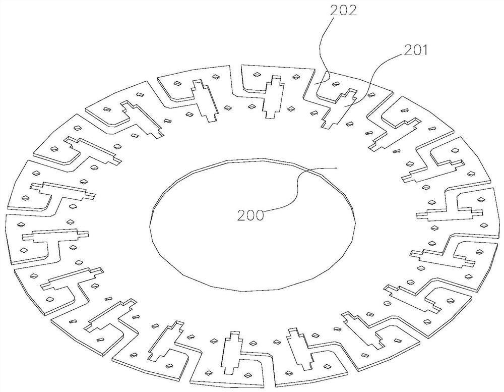
The invention discloses a dynamic and static transfer signal connection supporting device and a digital signal dynamic and static transfer device. The dynamic and static transfer signal connecting and supporting device comprises a connecting and supporting device body. The connecting and supporting device body is provided with a plurality of first fixing structures used for fixing first signal connectors, a plurality of second fixing structures used for fixing second signal connectors, a wiring space used for containing connecting wires and a plurality of wire outlet channels communicated with the wiring space. Each first fixing structure corresponds to at least one second fixing structure, and a connecting wire connected with the first signal connector and the second signal connector can be led out through the wire outlet channels. According to the digital signal dynamic and static transfer device provided by the invention, the mounting areas of the signal joints are uniformly distributed in the circumferential direction by the dynamic and static transfer signal connecting and supporting device, so that the digital signal dynamic and static transfer device can well adapt to different motion working conditions of rotating machinery.

Description

technical field [0001] The invention relates to a supporting device, in particular to a dynamic and static relay signal connecting support device and a digital signal dynamic and static relay device, belonging to the technical field of mechanical rotary motion. Background technique [0002] In the rotary motion mechanism, it is often required to be able to control the precise information status of each component on the motion mechanism, and it needs to cooperate with the corresponding sensing device. At the same time, the signal generated by the sensing device in motion needs to be exported to a signal terminal through a set of lines through the motion mechanism. Signal analysis and processing. In this case, there is a signal output from the moving mechanism to a static port. [0003] In the traditional rotary motion mechanism, the dynamic and static signals are connected through the line terminals, and it is very cumbersome and time-consuming to repair or replace the lines...

Claims


Application Information

Patent Timeline
Patent Type & Authority Applications(China)
IPC IPC(8): H01R35/00H01R13/514H01R13/46H01R24/00H02G3/02
CPCH01R35/00H01R13/514H01R13/46H01R24/00H02G3/02
Inventor 安旭杨宇强郁君健
Owner SUZHOU SILAIKE INTELLIGENT MOLD MFG CO LTD
Learn More