
Ultrasonic power supply and power supply method thereof

A power supply method and ultrasonic technology, which can be applied in the direction of conversion equipment that can be converted into DC without intermediate conversion, and can solve the problems of poor working stability of ultrasonic power supply and poor linearity of output power.

Active Publication Date: 2021-06-22
KEYIZHAN INTELLIGENT EQUIP CO LTD +1
View PDF9 Cites 0 Cited by
  • Summary
  • Abstract
  • Description
  • Claims
  • Application Information

AI Technical Summary

Problems solved by technology

[0004] This application provides an ultrasonic power supply and its power supply method, which solves the technical problem that the output power linearity of the existing ultrasonic power supply is poor, resulting in poor working stability of the ultrasonic power supply

Method used


Image

  • Ultrasonic power supply and power supply method thereof
  • Ultrasonic power supply and power supply method thereof
  • Ultrasonic power supply and power supply method thereof

Examples


no. 1 example

[0056] The above is the first embodiment of the ultrasonic power supply provided by the embodiment of the present application, and the following is the second embodiment of the ultrasonic power supply provided by the embodiment of the present application.

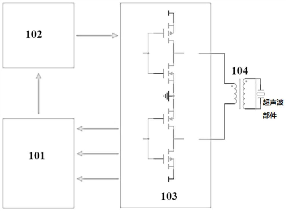
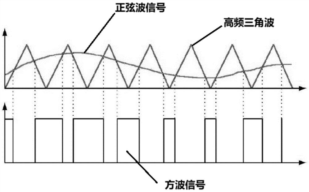
[0057] The ultrasonic power supply in the second embodiment includes: a main control unit 101, a first modulator 102, a power amplifier 103 and a coupler 104; the main control unit 101 is used to generate a preset signal; the first modulator 102 is used to The preset signal is pulse width modulated to obtain an electric pulse; specifically, the first modulator 102 is specifically a sine wave modulator, and the sine wave modulator is specifically used to perform pulse width modulation on a sine wave to obtain an electric pulse; the power amplifier 103, It is used to amplify the electric pulse and output the amplified electric pulse to the coupler 104; the output end of the coupler 104 is used to connect the ultrasonic compone...

Embodiment approach

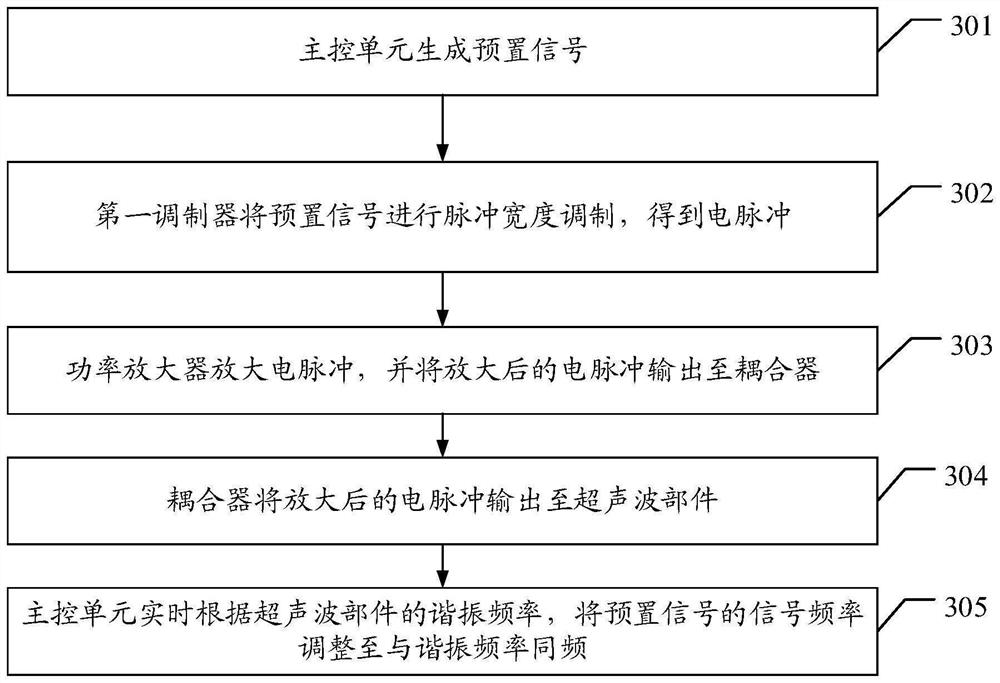
[0082] Obtain the resonance current of the ultrasonic component in real time, where the resonance current is the current of the ultrasonic component at the resonance frequency;

[0083] Calculate the current absolute value of the current difference between the resonant current and the signal current corresponding to the preset signal;

[0084] When it is determined that the absolute value of the current is greater than the second preset (preset current threshold), the signal current corresponding to the preset signal is adjusted to be equal to the resonant current, so that the frequency of the adjusted signal is the same as the resonant frequency.

[0085] It should be noted that, as can be seen from the above, the adjustment of the signal frequency of the preset signal can be realized by adjusting the signal frequency or by adjusting the signal current, and those skilled in the art can make a selection according to needs.

[0086] like Figure 4 As shown, obtaining the reson...


PUM


Abstract

The invention discloses an ultrasonic power supply and a power supply method thereof. The ultrasonic power supply comprises a main control unit, a first modulator, a power amplifier and a coupler, the main control unit is used for generating a preset signal; the first modulator is used for performing pulse width modulation on the preset signal to obtain an electric pulse; the power amplifier is used for amplifying the electric pulse and outputting the amplified electric pulse to the coupler; the output end of the coupler is used for being connected with an ultrasonic component. According to the present invention, the technical problem that the working stability of an existing ultrasonic power supply is worse due to the fact that the output power linearity of the existing ultrasonic power supply is poor, is solved.

Description

technical field [0001] The present application relates to the technical field of ultrasonic processing, in particular to an ultrasonic power supply and a power supply method thereof. Background technique [0002] With the development of modern machining technology, ultrasonic machining technology is widely used in precision machining, such as diamond, ceramics, glass, hard alloy, stainless steel, titanium alloy and other fields, and has achieved good processing results. [0003] As the basic components in ultrasonic machining, ultrasonic tool holder and ultrasonic welding parts will directly affect the processing efficiency when their stable work. The ultrasonic power supply is a device used to provide ultrasonic energy to the ultrasonic tool holder or ultrasonic welded parts. For an ultrasonic toolholder or ultrasonic weldment to work properly, the ultrasonic power supply must match the operating frequency of the ultrasonic toolholder or ultrasonic weldment. However, the ...

Claims


Application Information

Patent Timeline
IPC IPC(8): H02M5/16
CPCH02M5/16
Inventor 颜炳姜李伟秋何渐坚
Owner KEYIZHAN INTELLIGENT EQUIP CO LTD
Learn More