Supercharge Your Innovation With Domain-Expert AI Agents!

Particle detection device, dust collector as well as control method and control device of dust collector

A particle detection and vacuum cleaner technology, which is applied to the installation of vacuum cleaners, electrical equipment, cleaning equipment, etc., can solve the problems of dust sensitivity, inability to subdivide and adjust, and excessive dust

Inactive Publication Date: 2021-06-25
JIANGSU MIDEA CLEANING APPLIANCES +1
View PDF0 Cites 0 Cited by
  • Summary
  • Abstract
  • Description
  • Claims
  • Application Information

AI Technical Summary

Benefits of technology

This technology helps measure how well an object has been made up from its own material. It converts electrical energy into another form called inductive (inductively) waves through various means such as transformers or other devices. These waveforms are then analyzed with different techniques like voltage comparisons between them. By comparing these results against previous data sets, it becomes possible to determine if there was anything wrong during manufacturing processes.

Problems solved by technology

This patented technology solves this issue where when an automatic cleaners are used with high levels of particulate matter (PM) they may cause damage or wear down their components due to excessive exposure during operation. To solve these issues, current devices have difficulty detecting small particles caused by airborne pollution from indoor environments such as homes without being able to determine which parts require more maintenance than others.

Method used


Image

  • Particle detection device, dust collector as well as control method and control device of dust collector
  • Particle detection device, dust collector as well as control method and control device of dust collector
  • Particle detection device, dust collector as well as control method and control device of dust collector

Examples


Embodiment Construction

[0050] In the following, only some exemplary embodiments are briefly described. As those skilled in the art would realize, the described embodiments may be modified in various different ways, all without departing from the spirit or scope of the present application. Accordingly, the drawings and descriptions are to be regarded as illustrative in nature and not restrictive.

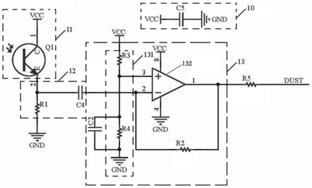
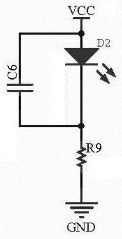
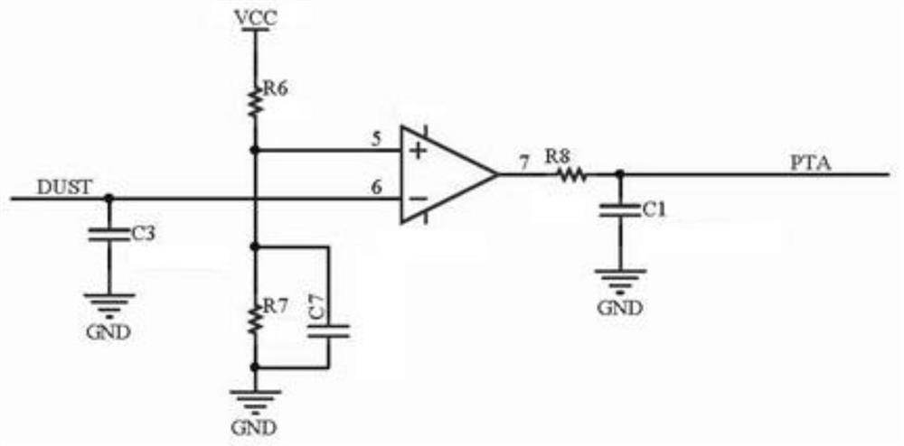
[0051] Figure 1-3 A schematic circuit diagram of a particle detection device according to an embodiment of the present application is shown. Such as Figure 1-3 As shown, the particle detection device of this embodiment includes: a particle sensing circuit 11 , a differential amplifier circuit 12 and a signal comparison circuit 13 .

[0052] The particle sensing circuit 11 is used for sensing particles and generating sensing signals. The particle sensing circuit 11 of the present application may be any sensing circuit capable of sensing particles, such as a light signal sensing circuit, a sound signal...


PUM


Abstract

The invention provides a particle detection device, a dust collector as well as a control method and control device of a dust collector. The particle detection device comprises a particle induction circuit, a differential amplification circuit and a signal comparison circuit; the particle induction circuit is used for inducing particles and generating an induction signal; the differential amplification circuit is connected with the output end of the particle induction circuit and used for amplifying the induction signal generated by the particle induction circuit; the differential amplification circuit comprises a first resistor and a first capacitor, one end of the first resistor is connected with the output end of the particle induction circuit, and the other end of the first resistor is grounded; one end of the first capacitor is connected with the output end of the particle induction circuit, and the other end of the first capacitor forms the output end of the differential amplification circuit; and the signal comparison circuit is connected with the output end of the differential amplification circuit and is used for comparing the amplified induction signal with a preset signal and outputting an induction trigger signal. The amplification factor of the differential amplification circuit can be reduced, and false triggering is prevented.

Description


Claims


Application Information

Patent Timeline
Owner JIANGSU MIDEA CLEANING APPLIANCES
Features
  • R&D
  • Intellectual Property
  • Life Sciences
  • Materials
  • Tech Scout
  • Unparalleled Data Quality
  • Higher Quality Content
  • 60% Fewer Hallucinations
Learn More