
Optical filter dust removal device for intelligent manufacturing

A technology of dust removal device and intelligent manufacturing, applied in cleaning methods and utensils, chemical instruments and methods, etc., can solve the problems of dust residue, labor-intensive, unclean cleaning, etc., and achieve the effect of preventing secondary pollution

Active Publication Date: 2021-06-25
江西百宏光电科技有限公司
View PDF3 Cites 0 Cited by
  • Summary
  • Abstract
  • Description
  • Claims
  • Application Information

AI Technical Summary

Problems solved by technology

[0005] In order to overcome the manual way of cleaning requires a lot of manpower and low work efficiency, there will be a small amount of dust residue and the shortcomings of unclean cleaning through manual cleaning. The technical problem to be solved is: to provide an automatic Cleaning, high working efficiency, cleaner cleaning and good working quality Filter dust removal device for intelligent manufacturing

Method used


Image

  • Optical filter dust removal device for intelligent manufacturing
  • Optical filter dust removal device for intelligent manufacturing
  • Optical filter dust removal device for intelligent manufacturing

Examples


Embodiment 1

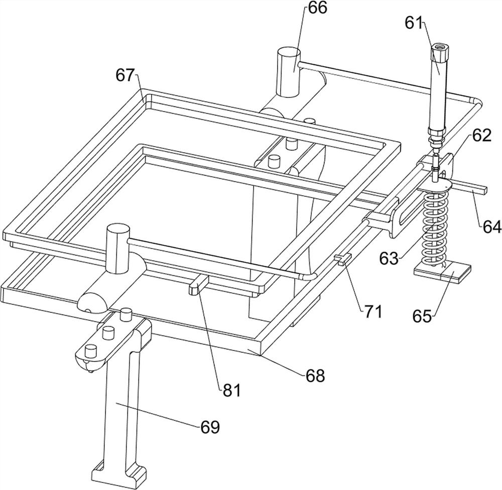
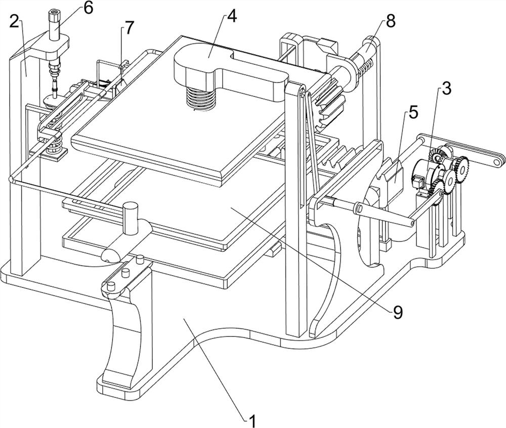
[0071] A filter dust removal device for intelligent manufacturing, such as figure 1 As shown, it includes a base plate 1, a first support frame 2, a driving mechanism 3 and a dust removal mechanism 4. The first support frame 2 is provided on the left side of the top of the base plate 1, and the drive mechanism 3 is provided on the right rear side of the top of the base plate 1. The top of the base plate 1 The right side is provided with dust removal mechanism 4.

[0072] Such as figure 2 As shown, the driving mechanism 3 includes a fixed seat 31, a motor 32, a sector gear 33, a first gear 34, a second support frame 35 and a transmission rod 36, and the right rear side of the top of the bottom plate 1 is provided with a fixed seat 31, and the top of the fixed seat 31 A motor 32 is provided, and a second support frame 35 is provided on the right rear side of the top of the base plate 1. A sector gear 33 is rotatably arranged on the second support frame 35. The drive shaft of t...

Embodiment 2

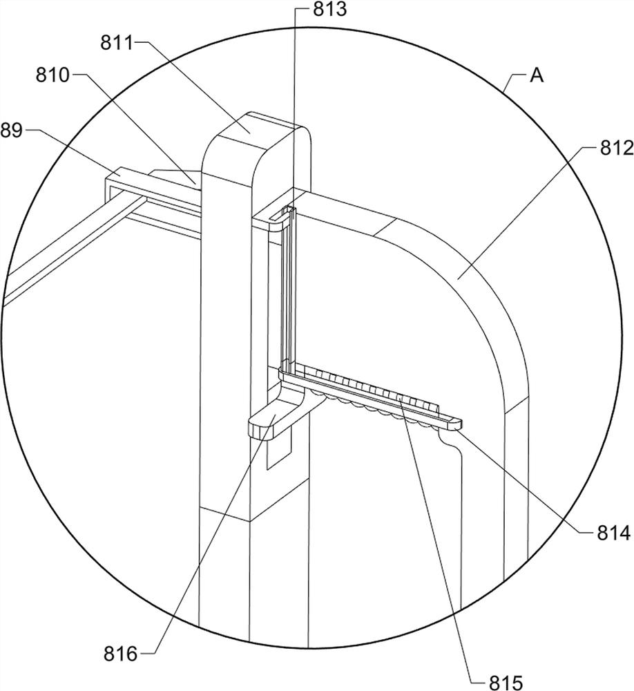
[0076] On the basis of Example 1, such as Figure 4 As shown, a propulsion mechanism 5 is also included, and the propulsion mechanism 5 includes a first fixed frame 51, a second gear 52, a bevel gear set 53, a crank connecting rod set 54, a transmission connecting rod 55, a rack 56, a third opening Slotted sliding frame 57, support bar 510 and first slotted sliding bar 511, base plate 1 top right rear side is provided with two first fixed frames 51, and the first fixed frame 51 on the front side is provided with the second gear 52 in rotation, A bevel gear set 53 is rotatably connected between the transmission shaft of the second gear 52 and the first fixed frame 51 on the rear side. The right side of the top of the base plate 1 is provided with a first slotted slide bar 511, which slides on the first slotted slide bar 511. A support rod 510 is arranged in the formula, a third slotted sliding frame 57 is provided on the right side of the bottom plate 1 top, a rack 56 is provid...


PUM


Abstract

The invention relates to a dust removal device, in particular to an optical filter dust removal device for intelligent manufacturing. The technical problem to be solved is to provide the optical filter dust removal device for intelligent manufacturing, which is capable of achieving automatic cleaning, high in working efficiency, cleaner in cleaning and good in working quality. According to the technical scheme of the optical filter dust removal device for intelligent manufacturing, the optical filter dust removal device for intelligent manufacturing comprises a bottom plate, a driving mechanism and a dust removal mechanism, wherein a first supporting frame is arranged on one side of the top of the bottom plate; the driving mechanism is arranged on one side of the top of the bottom plate; and the dust removal mechanism is arranged on one side of the top of the bottom plate. Through the cooperation between the driving mechanism and the dust removal mechanism which are arranged, the dust removal work of an optical filter can be completed; and the optical filter can be clamped through a third gear, an upper pressing plate and a lower bearing plate which are arranged, so that dust removal work on the optical filter is facilitated.

Description

technical field [0001] The invention relates to a dust removal device, in particular to a filter dust removal device for intelligent manufacturing. Background technique [0002] Optical filters are optical devices used to select the required radiation band, usually made of plastic or glass with special dyes added, red filters can only let red light pass through, and so on, so filters are widely used in photography world. [0003] The surface of the filter plate needs to be cleaned during production to avoid residual dust affecting the efficacy of the filter. At present, the dust on the surface of the filter is cleaned manually with a hand-held brush. This manual method It takes a lot of manpower to clean up, and the work efficiency is low. There will be a small amount of dust residue in the way of manual cleaning, and the cleaning is not clean. [0004] Therefore, it is necessary to design a filter dust removal device that can be automatically cleaned, has high work effici...

Claims


Application Information

Patent Timeline
Patent Type & Authority Applications(China)
IPC IPC(8): B08B7/00B08B13/00
CPCB08B7/0028B08B13/00Y02A50/2351
Inventor 田大志
Owner 江西百宏光电科技有限公司
Learn More